
There is a “personnel safety” practice that is very common in the design of process plants, but it is not the best design for “process safety,” and I forgot to mention this in my earlier Car-Seal article. Here is the setup. Do you see anything wrong with the pressure gauge arrangement?
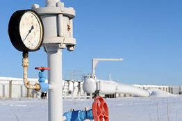
Plants like to use valves in their instrument loops so that maintenance on the instrument can be done safely. But this sets us up for a SERIOUS process safety incident. For example, the process above is protected by a high-pressure interlock. Only one safety system (a PI, PSH, and PT) sends the signal back to the control room. As shown above, the valve between the process and the gauge and transmitter (not shown in the photo) can potentially close the valve inadvertently. This would trap the pressure between the valve and the gauge and transmitter, thus “dumbing down” your safety system and your personnel. Personnel making their rounds would see the proper pressure on the gauge REGARDLESS of what the process pressure really is. Even the PLC or DCS would be “dumbed down” as it would not be allowed to see the actual process pressure. But it would also not go into alarm for a fault, as it is seeing a constant pressure that is within the Safe Operating Envelop. So the process pressure could be outside the Safe Operating Envelop, and no one would be the wiser, all because one small little valve is closed.
When we are presented with such a scenario, the logical thing is to Car-Seal the valve in the OPEN position. Also, if your process is handling a volatile liquid, don’t forget the need for a hydrostatic relief valve between the gauge and the valve, or there may be another problem!!!