
Flammable liquids are “volatile liquids” with relatively low boiling points. This means it does not take much to get these materials boiling, especially on a hot summer day. And just like that pot of boiling water on our stove, the flammable liquids in these above-ground tanks can generate tremendous volumes of flammable vapors, which can travel great distances and ignite. But the main concern is the boiling flammable liquid generating increased pressure in a tank that is NOT designed for pressure (e.g., atmospheric tank). OSHA, NFPA, and API all require these atmospheric tanks to have an appropriately sized EMERGENCY VENT and NORMAL BREATHING VENT.
In this article, I will focus on OSHA’s 1910.106 requirements since we all have FREE access to this standard. 1910.106(b)(2)(v) “Emergency relief venting for fire exposure for aboveground tanks” has some basic requirements for ALL ATMOSPHERIC ABOVEGROUND tanks that contain a flammable liquid (e.g., Flash Point < 100°F):
- have some form of construction or device that will relieve excessive internal pressure caused by exposure fires (this is called the “fire scenario” and is very popular term when discussing relief protection devices).
- in a vertical tank the “construction” (mentioned above) may take the form of
- a floating roof,
- lifter roof,
- a weak roof-to-shell seam (the weak roof-to-shell seam shall be constructed to fail preferential to any other seam)
- other approved pressure relieving construction.
- where the entire dependence for emergency relief is placed upon “pressure relieving devices”, the total venting capacity of BOTH normal and emergency vents must be enough to prevent rupture of the shell or bottom of the tank if vertical, or of the shell or heads if horizontal.
- If unstable liquids (a liquid which in the pure state or as commercially produced or transported will vigorously polymerize, decompose, condense, or will become self-reactive under conditions of shocks, pressure, or temperature) are stored, the effects of heat or gas resulting from polymerization, decomposition, condensation, or self-reactivity miust be taken into account.
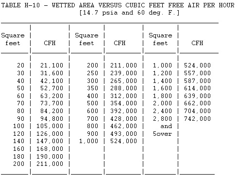
- The TOTAL capacity of BOTH normal and emergency venting devices can NOT be less than that derived from Table H-10 (see below).
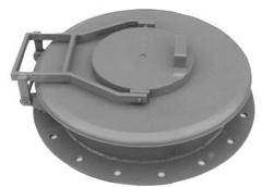
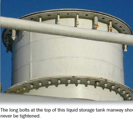
- Such device may be a self-closing manhole cover, or one using long bolts that permit the cover to lift under internal pressure, or an additional or larger relief valve or valves.(shown below – photo courtesy of NFA)
- The wetted area of the tank shall be calculated on the basis of 55 percent of the total exposed area of a sphere or spheroid, 75 percent of the total exposed area of a horizontal tank and the first 30 feet above grade of the exposed shell area of a vertical tank.
- The outlet of ALL vents and vent drains on tanks equipped with emergency venting to permit pressures exceeding 2.5 p.s.i.g. must be arranged to discharge in such a way as to prevent localized overheating of any part of the tank, in the event vapors from such vents are ignited.
- Each commercial tank venting device MUST have stamped on it:
- the opening pressure
- the pressure at which the valve reaches the full open position and
- the flow capacity at the latter pressure, expressed in cubic feet per hour of air at 60ºF and at a pressure of 14.7 p.s.i.a.
- The flow capacity of tank venting devices 12 inches and smaller in nominal pipe size must be determined by actual test of each type and size of vent.These flow tests may be conducted by the manufacturer if certified by a qualified impartial observer, may be conducted by an outside agency. The flow capacity of tank venting devices larger than 12 inches nominal pipe size, including manhole covers with long bolts or equivalent, may be calculated provided that the opening pressure is actually measured, the rating pressure and corresponding free orifice area are stated, the word “calculated” appears on the nameplate, and the computation is based on a flow coefficient of 0.5 applied to the rated orifice area.
By the way, before I go any further, all the above info regarding the emergency vent sizing, venting configuration, etc., would HAVE TO BE DOCUMENTED for those processes that contain over 10,000 pounds of the flammable liquid (not taking into consideration the “Meer Decision” to exempt the atmospheric storage tank(s)).
Once we have the type and sizing of the emergency venting taken care of, we need to discuss “normal venting” for the tank. This vent plays a major role in allowing the tank to “breathe” as it is filled with product and when it is withdrawn. Let’s take a look at the regulatory and code requirements for these “normal vents.”
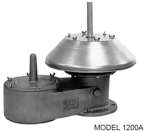
Atmospheric storage tanks must be adequately vented to prevent the development of VACUUM or PRESSURE sufficient to distort the roof of a cone roof tank or exceed the design pressure in the case of other atmospheric tanks as a result of filling, emptying, and/or atmospheric temperature changes. Normal vents must be sized either per the American Petroleum Institute Standard 2000 (1968), Venting Atmospheric and Low-Pressure Storage Tanks, or other accepted standards. The vent must be at least as large as the filling or withdrawal connection, whichever is larger, but in no case less than 1.25″ nominal inside diameter. Suppose any tank has more than one (1) fill or withdrawal connection, AND simultaneous filling or withdrawal can be made. In that case, the vent size MUST be based on the maximum anticipated simultaneous flow. Unless the vent is designed to limit the internal pressure to 2.5 psi or less, the outlet of the vent(s) and vent drain(s) must be arranged to discharge in such a manner as to prevent localized overheating of any part of the tank in the event vapors from such vents are ignited (i.e., no goosenecks on vent discharge). If your tank(s) or pressure vessel(s) store Class IA flammable liquids (FP< 73ºF and BP<100ºF), they must be equipped with venting devices that are NORMALLY CLOSED except when venting to pressure or vacuum conditions. Tanks and pressure vessels storing Class IB (FP<73ºF and BP> 100ºF) and IC (FP>73ºF and BP<100ºF) liquids must be equipped with venting devices that are NORMALLY closed except when venting under pressure or vacuum conditions, OR with approved flame arresters. Please note that a device that is “normally closed” is often called a “conservation vent” as it conserves the vapors within the tank (see below on the left). The device below, on the right, is a combination conservation vent and a flame arrester. The flame arrester is the “fat part” just above the flange at the base of the unit. This would be called an “in-line” arrester. The device in the middle is an “end of line” flame arrester and will sit at the vent line. This is strictly a flame arrester and is normally OPEN.
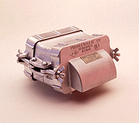
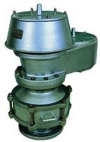
Exemption: Tanks of 3,000 bbls. Capacity or less containing crude petroleum in crude-producing areas; and, outside aboveground atmospheric tanks under 1,000 gallons capacity containing other than Class IA flammable liquids may have open vents. Flame arresters or venting devices may be omitted for Class IB and IC liquids where conditions are such that their use may, in case of obstruction, result in tank damage.
Think this is overkill? Let me demonstrate what happens when emergency venting is NOT sized and/or installed properly! CAUTION: You need to have the volume turned up to hear the incident, but then you may want to mute the sound immediately after the 2nd tank explodes, as the first tank and it’s associated piping land on the back of the videographer’s van, and he is a bit unhappy and excited by it all and lets a few choice expletives escape his mouth. For the emergency responders who view the video – pay attention to the time span (2.5 minutes) from the two (2) tank explosions and the ALL CLEAR being sounded. You can also see that after the tank failure, the entire tank farm is on fire now and with each tank on fire. Things went from bad to horrible in a very short time, all because emergency venting was either improperly installed or non-existent.
This video is a perfect example of what happens when the tank’s emergency relief system FAILS. The tank was supposed to have a weak roof-to-shell seam, but this system FAILED for unknown reasons. The tank next to it, performed exactly as designed, blowing the roof off and leaving the walls and dish intact, thus not releasing its flammable contents. PAY CLOSE ATTENTION to the outcome of the failed emergency venting! Notice TWO VERY IMPORTANT OUTCOMES: 1) the tank launches some 100′ into the air and 2) the wall of fire that overtakes the dike wall and makes contact with the fire truck. This video also demonstrates why OSHA and other codes SPECIFICALLY PROHIBIT “weak roof-to-shell seam” as the means for emergency venting on INDOOR STORAGE TANKS!
1910.106(b)(4)(ii) “Vents.” Vents for tanks inside of buildings shall be as provided in subparagraphs (2) (iv), (v), (vi)(b), and (3)(iv) of this paragraph, except that emergency venting by the use of weak roof seams on tanks shall not be permitted. Vents shall discharge vapors outside the buildings.
Tank venting is ABSOLUTELY a CRITICAL PATH in the safe storage of flammable liquids. Although not clear in 1910.106 or NFPA 30, process vessels used in processing the flammable liquids should, without a doubt, meet the same design as the storage tanks. A simple check of your tanks/vessels is a great start. The emergency vents will be a rather larger opening with some cover that is either just sitting on the opening with a cable attaching the lid to the tank, or the lid may be hinged or “long bolted” design as shown above.