
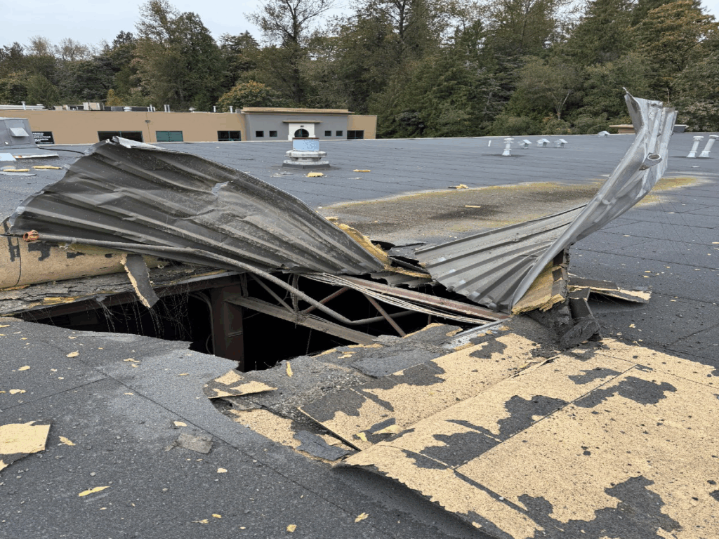
I am sharing this incident as we continue to find air receivers that are 20+ years old and have never once been inspected as a pressure vessel. We even see this in PSM/RMP-covered facilities – the facility does a nice job on their process pressure vessels, but overlooks their air receivers. Air receivers have a history of failures, as they just are rarely recognized as a hazard. As this event makes clear, they present a catastrophic hazard.
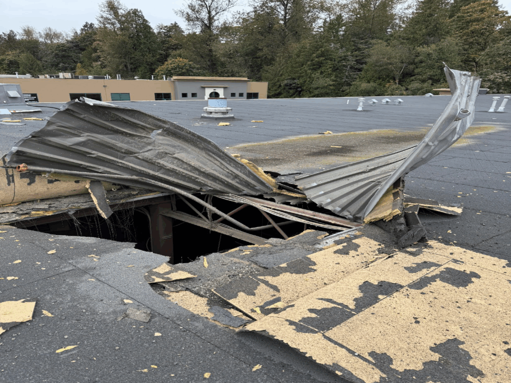
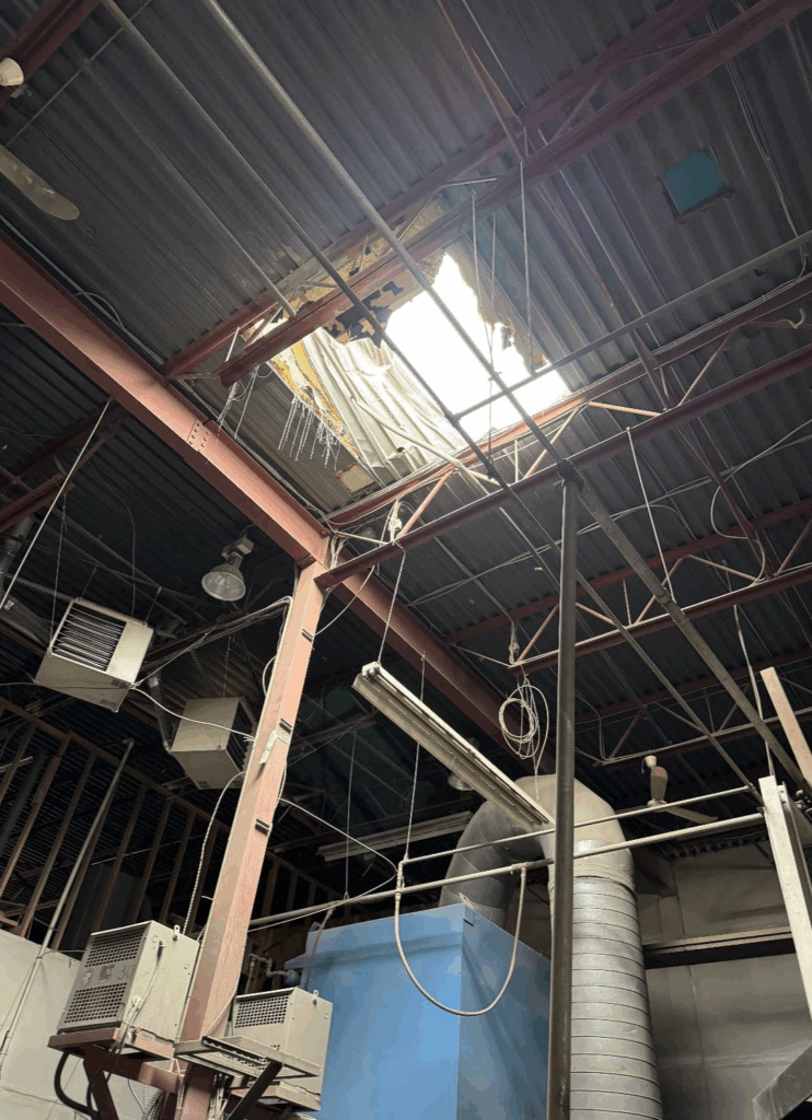
An air receiver tank in a sandblasting shop suffered a catastrophic failure during an over-pressure event. The bottom of the tank blew off and crushed the pallet it was sitting on, and the body of the tank was propelled vertically 9 meters (30’) through the roof of the building. The tank collided with and disabled the sprinkler system before ripping a 3-meter square (10’ x 10’) hole in the roof. A large contractor-grade 300 psi airline that was attached to the tank was pulled apart until it ruptured. The damaged sprinkler system activated, flooding the shop space and adjoining businesses, causing the main electrical power to be shut down. The force of the blast blew windows out between the shop space and the adjoining offices.
The primary cause of the vessel failure was that Supply Tank 2 was installed in a high-pressure application, which was neither designed nor constructed. As the system was charging for the first time, the tank could not withstand the pressure and separated at the weld joint joining the bottom head and the shell at the vessel’s base.
The system included: a 60-horsepower fixed speed air compressor (575v / 3phase) that is meant to maintain a steady output of 125 psi. The compressor was connected to an electric dryer by a 2” ID flexible airline. The airlines were all contractor grade and had a pressure rating of 300 psi. There were ball-valve disconnects located on the intake and the output of the dryer, so it could be isolated from either the compressor or the rest of the system. The output from the dryer ran through a second 2” airline to a vertical air receiver, “Supply Tank 1”.
Supply Tank 1 was pressure vessel, with a maximum allowable working pressure (MAWP) of 200 psi, protected by a safety relief valve set at 150 psi, and was bolted securely to the concrete floor. It was compliant to applicable codes and, with continued annual maintenance, was appropriate for the application.
By design, the operating pressure (125 psi) would not reach the set pressure of the relief valve (150 psi), and if it did, the safety relief valve, if properly functioning, would open. This would prevent any overpressure event in the tank itself, which
had a MAWP of 200 psi.
From Supply Tank 1 another flexible 2” airline ran to a galvanized black iron piping system than ran overhead though a series of tees, distributing the air to four different stations in the shop: a large sandblasting room with an ASME rated sandblasting pot, two smaller sandblasting cabinets, a paint room, and fourth station outside.
In the morning, the shop general manager would turn on the air compressor and load the system, watching the gauge until it reached 125 psi. At 125 psi the compressor would automatically cut out, and it would cut back in as needed, as the supply was used.
The owners wanted to augment the capacity of the compressed air system by installing two more air receivers. To do so in a manner that was both safe and code-compliant, the owner would need to ensure the following:
1) That the system, which is considered regulated equipment, is installed by an appropriately licensed and qualified contractor.
2) That all pressure vessels introduced to the system meet jurisdictional regulations and code requirements, both in their manufacture and installation. This includes ensuring they come with correct identifying information and documentation so that their maximum allowable working pressures (MAWP) and capacities can be determined.
3) That every pressure vessel is equipped with a code-compliant pressure relieving device (PRD), and each PRD is installed in such a way that it provides adequate overpressure protection for the pressure vessel it is protecting.
4) That PRDs such as safety relief valves (SRVs) are maintained regularly, tested for functionality, and replaced within their service interval. The service interval for an air receiver is five years. Each pressure vessel is required to have at least one pressure relieving device installed directly on the vessel, with a set pressure that is below the pressure vessel’s MAWP, and adequate capacity to protect it during an overpressure event.
5) That regulated pressure vessels have the required operating permits and inspections.
6) That any used equipment, as well as meeting the above requirements, undergoes rigorous inspection and testing before being returned to service.
The two extra tanks, “Supply Tank 2” and “Supply Tank 3”, were intended to charge simultaneously with Supply Tank 1, tripling the amount of stored compressed air that was available, and thus allowing multiple processes (sandblasting, painting, etc.) to occur at the same time.
“Supply Tank 2” was a vertical tank 1.82 meters (72”) tall and 1.1 meters (43”) in diameter. It was connected to Supply Tank 1 by a 2” flexible hose in with a ball valve disconnect between them, at the intake of Supply Tank 2. Supply Tank 2 was not secured to the floor but had a flat bottom and was strapped to a wooden pallet beside Supply Tank 1. Supply Tank 2 was not a recognized ASME pressure vessel design, and did not have a rating plate of any description. The MAWP, registration information, age, and manufacturer, were unknown. Supply Tank 2 was not provided with any overpressure protection in the form of a safety relief valve installed at the vessel.
The owners painted “Supply Tank 3” dark blue and installed it on the west side of the compressor near the sandblasting room. Supply Tank 3 measured 3 meters (120”) long, and 0.91 meters (36”) in diameter. It was connected to the system by 2” galvanized piping that ran overhead, having teed off from Supply Tank 1. Supply Tank 3 had a rating plate that specified a MAWP of 100 psi, and that it was built in 1957, but it was not an ASME nameplate and did not indicate the code of construction. Supply Tank 3 was suspended by a lightweight angle iron frame that had been welded directly to the pressure vessel. Any after-market welding to a
pressure vessel is considered to have compromised the pressure barrier and is not permitted, unless the vessel is re-engineered and undergoes a repair and alteration procedure, which this one did not. There also appeared to be plug welds near the upper head, one of which showed evidence of leaking. No safety relief valve was installed with this vessel.
Failure scenario(s)
A sandblasting business began operations in 2015, with a compressed air system that was installed by a licensed contractor. In 2021 the owners relocated to a new 10,000 square foot space and reinstalled the compressed air system without using a contractor or obtaining the required pressure vessel operating permits.
To increase the capacity of the compressed air supply, the owners purchased two previously used tanks on a public website that is commonly used for buying and selling second-had items. The tanks were advertised as an “auxiliary air tank” and a “vertical auxiliary air or vacuum tank”, were sold together by the same individual, and were in similar condition. The owners installed the two tanks in the existing system without using a licensed contractor.
The owners were unaware that Technical Safety BC provided regulatory oversight for pressure equipment. They were also unaware of any licensing requirements for the system or permitting requirements for the pressure vessels. They did not consider whether the tanks they were purchasing were designed for a compressed air system application, or whether they were in acceptable condition, but assumed that they would be adequate, based on the seller’s description. The tanks were sold with no identifying documentation.
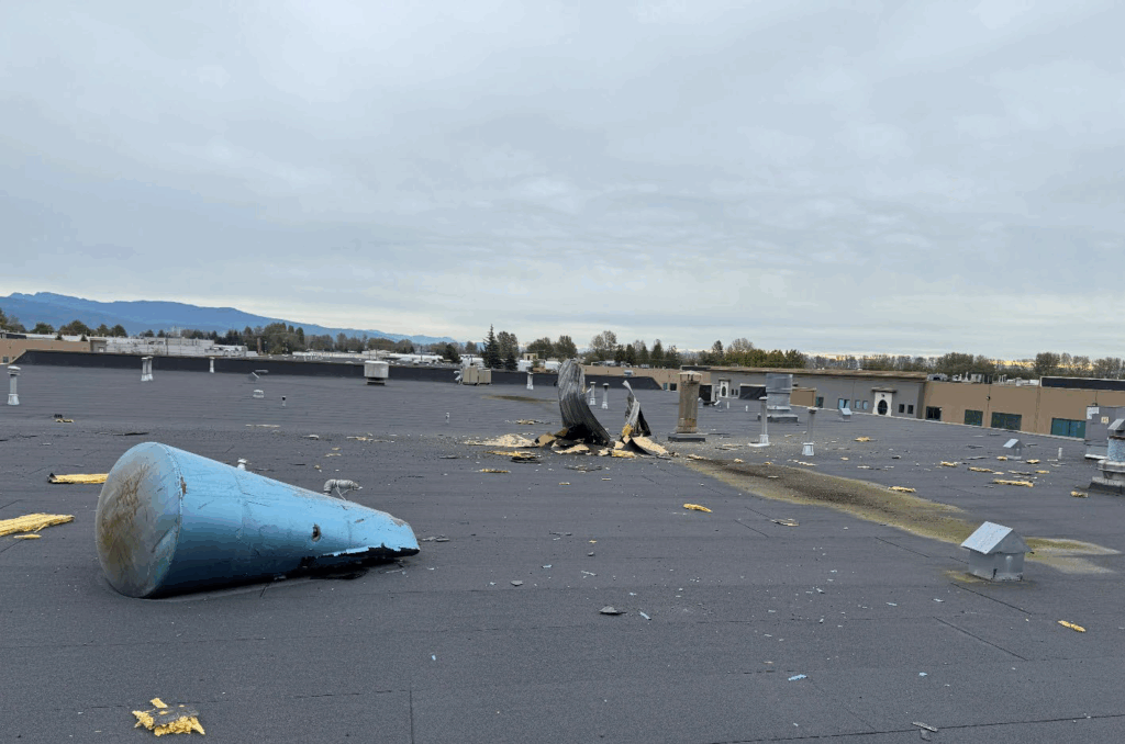
On October 1, 2024, at approximately 8:40am, the Manager started the compressor and began charging the system for the first time after the recent installation of the two second-hand supply tanks. After approximately 45 seconds loading the system, Supply Tank 2 ruptured at the base. The circumferential weld joining the bottom head of the vessel with the shell failed entirely, separating the bottom from the body of the tank. This sudden explosive failure of the pressure barrier caused the vessel to be launched vertically approximately 30’ into the air. Supply Tank 2 collided with a section of the sprinkler system, disabling it, then penetrated the roof and exited the building, creating a 3-meter by 3-meter (10’ x 10’) hole. The vessel travelled to an unknown altitude before reversing direction and landing on the roof approximately 5 meters from the hole.
The manager was charging the compressor two meters from Supply Tank 2 when the bottom blew off and it rocketed through the roof. He was kneeling behind Supply Tank 1 at the time, which was bolted to the concrete floor, and shielded him from most of the force of the blast. He was uninjured, but does not remember the sound of the blast, only that “the room was suddenly filled with dust”.
When Supply Tank 2 was propelled through the roof, the 2” flexible airline that connected Supply Tanks 2 and 1 was stretched to its breaking point and ruptured at the output nozzle. The pallet that it had been sitting on was crushed, and the bottom head of the vessel remained on the pallet. When the overhead sprinkler system was impacted, it activated, flooding the building. The main electrical power was then disabled.
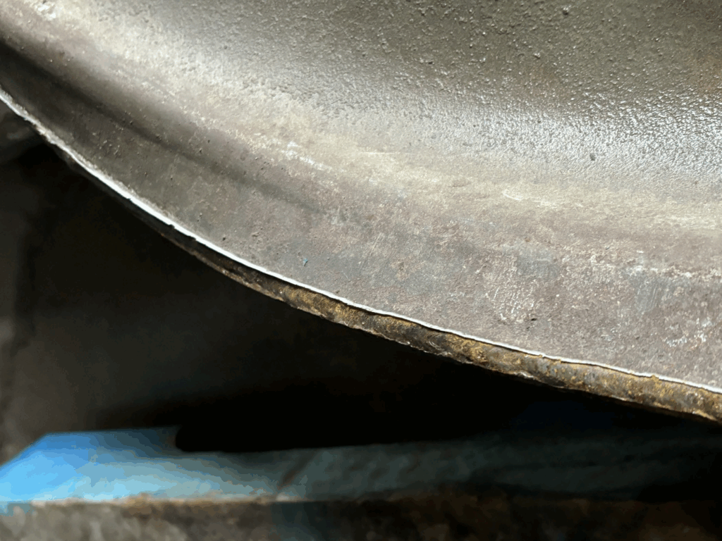
Examination of Supply Tank 2 after the incident confirmed that it was not designed or constructed as an ASME Section VIII Div 1 pressure vessel and was neither intended nor suitable for compressed air service. The vessel had an internal baffle attachment that is typical for liquid or steam service. The lower head appeared to be convex and had a factory break in the circumference giving the head a folded-down rim. The head appeared to have fit inside the shell and was attached with a single pass fillet weld holding it in place. Neither head is of a geometry typical of a code-rated pressure vessel. The longitudinal seam in the shell was a single pass seal weld on the outside of the vessel with no gap or joint penetration, and no welding on the inside.
The tank that failed was purchased as one of two obtained together from the same source. The second tank of the pair, Supply Tank 3, had a nameplate indicating a manufacture date of 1957. During examination of Supply Tank 3, multiple non-compliances were observed including design alteration, welding directly to the pressure barrier, and holes drilled in the shell. It was noted that the maximum allowable working pressure of the vessel was 100 psi, but it was installed in a system that was charged to 125 psi, dramatically increasing the probability of an overpressure event. No safety relief was installed with this tank, further increasing the risk. As well, a home-made angle iron frame had been welded directly to the shell of the pressure vessel, a practice which compromises the shell integrity and renders it unfit for service. After the incident, when Supply Tank 3 was removed from service for safety reasons, it was discovered that three 3/8” holes had been drilled in the shell of the vessel, a practice generally employed to render a pressure vessel unusable when it has been decommissioned. The holes were subsequently
hidden by bolts and washers placed in the holes, and affixed in position with silicon, before being sold on the website.
Facts and evidence
Interview 1: Owner 1, Owner 2, Manager.
The two owners and the manager were in agreement on the facts of the interview and stated the following:
- They did not know that pressure vessels were regulated equipment and required permits.
- They did not know that the piping system was regulated work and required a licensed contractor to install it.
- They had incorporated the business in 2016 and had moved in 2021.
- When they moved, the compressed air system was not installed by a licensed contractor. The owners moved and reinstalled it themselves.
- The original system was installed by a contractor, engaged by the original owner of the business.
- They did not know that any maintenance was required on pressure vessels or compressor equipment. “No service is required on pressure vessels. Or not any that we’re aware of”.
- They had never had the equipment tested or serviced.
- The safety relief valve on the ASME receiver (Supply Tank 1) had not been tested or replaced in nine years. (servicing or replacement is required every five years, in accordance with CSA B51 Table 5).
- The incident occurred during the first time that the system was being charged after the owners had installed the two second-hand tanks.
- The tanks were purchased from an individual who was advertising them as “auxiliary air tanks” on a website.
- There was no documentation supplied with the second-hand tanks (Supply Tank 2 and Supply Tank 3). and no documentation available on site for Supply Tank 1.
- There was no equipment maintenance records on site for the air system.
- Facility manager drew a sketch of the system.
Interview 3: WorkSafe Officer
• Confirmed that when the vessel impacted and activated the sprinkler system, the subsequent flooding posed an electrical hazard and necessitated that the main electrical source be shut down until rendered safe.
Interview 4: Insurance Investigator
• Provided photos of the tanks prior to the incident from original online advertisement.
• Provided photos from the roof.
• Provided access to the garage storage facility where the vessel was being kept.
Site Observations:
• Equipment was found installed with worm-drive hose clamps, that were not code-compliant, holding the hoses to the fittings and tank nozzles.
• The tank that failed (Supply Tank 2) was not secured to the floor.
• The sole pressure relief device in the system (Supply Tank 1) had never been serviced and has not been proved operational.
• The two second-hand tanks were found with no pressure relief devices installed, meaning they did not have adequate overpressure protection.
• No nameplate was found on Supply Tank 2.
• A nameplate was discovered on the bottom head of Supply Tank 3, which showed the MAWP as 100 psi, manufactured in 1957.
• No documentation was available on site for any of the three tanks, and there were no maintenance records for the system available on site.
Examination of the carcass of Supply Tank 2 at Insurance Investigator’s laydown yard revealed:
- Length, 72”, diameter 42” to 44”, distorted. Shell is 2.96mm thick (calipers)
• The heads did not correspond to ASME Section VIII div 1 design principles. The dimensions of the top head were asymmetrical, indicating a high margin of error (Image 17).
• The presence of an internal baffle plate suggests liquid service, and examination of the carcass suggests it was designed for low-pressure use.
• The longitudinal weld in shell seam was a single pass from the outside, with no gap and no penetration. It was not a “pressure” weld (Image 13 & Image 14).
• The bottom head configuration was not immediately apparent because of the distortion, but it appears to have been a convex or concave piece with a factory break forming a rim around the circumference (Image 10). Marks on the shell and head indicate the head “rim” slid inside the vessel, and was seal welded with either a single-pass fillet weld or an edge weld.
• Two photos from the online ad showing the vessels for sale were recovered (Image 2 & Image 3). They have matching paint, which is common when vessels have been in the same installation. Supply Tank 3 has a data plate indicating it was built in 1957 by J Wood. An image search of Supply Tank 2 produced a drawing of a very similar tank, also by John Wood. It is labelled as a “water tank”. This connection supports the premise that both tanks are from the same original installation.
• Supply Tank 3 had holes drilled in the shell, that had been disguised by the insertion of bolts with wide washers, affixed with silicon. This is indicative of a tank that had been decommissioned in the past, then resurrected and sold back into service.
Causes and contributing factors
The primary cause of the vessel failure is that Supply Tank 2 was installed in a high-pressure application for which it was neither designed nor constructed. As the system was charging for the first time, the tank was unable to withstand the pressure and separated at the weld joint joining the bottom head and the shell at the base of the vessel.
The owners and manager lacked a basic knowledge of the regulatory requirements of their system, which manifested as multiple hazards and omissions. They purchased used equipment of unknown origin with no identifying information or documentation, which led to the wrong tank being installed for the application, resulting in a catastrophic failure.
No overpressure protection was provided for the tank, and Supply Tank 2’s MAWP and capacity were unknown. It is possible that the installation of a correct SRV may have prevented the vessel failure.
The condition of the tank was a likely contributing factor. The type and extent of stresses to which it was subjected in the past is unknown, and a rigorous inspection and testing process by a non-destructive examination (NDE) contractor was not undertaken prior to installation.
While multiple hazards were identified in association with Supply Tank 3, there is no evidence that these deficiencies contributed to the failure of Supply Tank 2. Supply Tank 1 was compliant in its installation but had not been adequately maintained. However, it is unlikely that the lack of maintenance directly contributed to the failure of Supply Tank 2.
Examination of the welding, joint configuration, and geometry of the failed vessel supports the conclusion that it was not designed or constructed to the standards necessary for compressed air service.
CLICK HERE for the full report and all photos.