
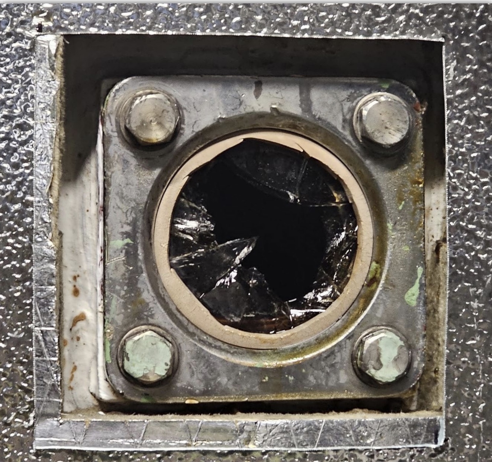
A pressure vessel at a food processing facility failed when a sight glass ruptured during an overpressure event, spraying hot liquid at 100 psi into the workspace. The vessel had been operating above its maximum allowable working pressure for weeks due to:
- clogged filters,
- bypassed safety interlocks, and
- a lack of maintenance on pressure relief valves.
Contributing factors included
- untrained staff,
- missing regulatory permits, and
- poor system design
which left parts of the vessel unprotected from overpressure.
The industrial food processing facility uses a mechanical system for the processing of a liquid food product.
Filtering system
The system incorporates pumps that force the liquid through piping and a multi-stage filtering system. At each of the filter vessels the liquid is pushed through cylindrical filter elements. The pressure vessels consist of two separate chambers separated by a tube sheet with multiple cylindrical filters installed. The tube sheet is sandwiched between two flanges that bolt the upper half and lower half of the filter body together. Fluid is pumped under pressure through the filter medium from the lower inlet section into the upper vessel section, where it is collected and piped to the next stage in the process. Each filter incorporates three sight glasses to provide a means of visually observing the contents and process inside the vessel. The filters were designed with a maximum allowable working pressure (MAWP) of 75 psi. The systems are typically operated under 40psi.
As the filter elements in the vessels become clogged with particulates, the flow through the filters is restricted and the operating pressure increases. When this occurs, the facility has a defined process for filter “regeneration” which requires the production process to be halted. The “regeneration” process clears the contaminants from the internal filter elements and restores process flow, reducing operating pressures.
Overpressure protection
To protect the filter vessels against overpressure, pressure relief valves (PRVs) are installed on the tops of the vessels. The PRVs use a spring to force a disk against a reseating surface to prevent flow through it and are set to open at 75psi (the maximum allowable operating pressure of the vessel). When pressure exceeds this setting, it will overcome the spring pressure and force the disc off the reseating surface and release the excess pressure by allowing flow through a piping system that is released to a safe location. When the pressure in the vessel reduces below the set pressure, the PRV’s spring will reseal the disc against the reseating surface and stop the flow.
Automated control system
In 2023, a new automated control system was implemented. It uses a computer human machine interface (HMI) to monitor and control the system, including the operation of valves and pumps, and monitoring of pressures, volumes, and flow. The system incorporates multiple safety and process interlocks including overpressure. The system first alerts operators with a warning alarm when the pressure in the filters exceeds 40psi and a second critical alarm if the pressure exceeds 70psi.
Code and regulations requirements
The Power Engineers, Boiler, Pressure Vessel and Refrigeration Safety Regulation (The regulation) for BC is applicable to pressure vessels with relief valves set at a pressure over 15psi (103kpa). The regulation defines a pressure vessel as: A vessel and its fittings, that is capable of being used to contain, store, distribute, transfer, distil, process or otherwise handle gas, vapour or liquids under pressure. The filter vessels used at the facility are regulated pressure vessels and are applicable to the regulation.
The regulation states that:
- The design of pressure vessels must be registered with a provincial safety manager.
- A person must hold an operating permit for each pressure vessel. The ASME boiler pressure vessel code Section VIII – Rules for construction of pressure vessels states:
- When a pressure relief device is provided, it shall prevent the pressure from rising more than 10% or 3psi above the maximum allowable working pressure of the vessel. (82.5psi for a pressure vessel with a 75psi MAWP).
- The pressure relief devices on all vessels shall be so installed that their proper functioning will not be hindered by the nature of the vessel’s contents. The currently adopted CSA B51 Boiler, pressure vessel, and pressure piping code states:
- The specifications pertaining to the design of pressure vessels shall be submitted to the regulatory authority in the province where the item is intended to be used.
- The owner shall establish a program that addresses the required inspection, testing, servicing, and replacement of pressure relief devices.
- The maximum service interval for reclosing pressure relief devises on the type of pressure vessels used as filters in the facility is 3 years.
Failure scenario(s)
The pressure vessels for the food processing system were manufactured and originally installed at the facility in the 1960’s. The pressure vessel had not been registered, an operating permit had not been obtained and the PRV was not part of a service program and had not been tested, serviced or replaced since its original installation as required in the regulations. This did not allow for the required regulatory oversight and potential assessments that may have identified and mitigated the overpressure hazards in the system.
The pressure vessel involved in the incident (Filter #4) was designed with a MAWP of 75 pounds per square inch (psi). The system was provided with overpressure protection by the use of a PRV that was set to open at 75psi to relieve excess pressure. The PRV was located at the top of the pressure vessel downstream of the pressure vessels internal filter elements. The transducer that measured the pressure in the system for the electronic operating and monitoring system was located upstream of the filter elements.
The typical operating pressure in the system was less that 40psi. When the filter elements in the pressure vessel became clogged with excessive particulates, the flow through the filters decreased and the pressure upstream of the filters increased. The operators have the ability to adjust the flow of material through the filters to control the operating pressures.
The operators for the system received training including review of the facility’s Task Hazard Analysis (THA) documents for system start up and filter recharging. The THA documents did not identify any operating pressure limits. The automated electronic operating and monitoring system incorporated a 40psi warning alarm to alert operators and a 70psi critical alarm to shut the system pumps down. The system allowed permissions for operators and mangers to bypass both of the alarms and shortly after the implementation of the system in 2023, both the warning alarm and critical alarm had been bypassed allowing for continued operation above those pressures.
For “at least a couple of weeks” leading up to the incident restrictions in the filter elements led to pressure in the system being operated up to 100 psi (25psi above the vessels MAWP) while maintaining a typical product flow rate. Operators had been raising concerns of product quality and the high operating pressure but only due to the high frequency of the required system shutdown and filter “rejuvenation” process to lower the pressures. No identification of an overpressure hazard was reported to have been raised.
Restricted filters caused higher pressure to be present on the upstream side of the filters where the pressure transducer measured for the automated system, but the pressure in the area downstream of the filter restriction, where the PRV was installed, was lower than the PRV set pressure and it did not open to relieve the excess pressure that was present upstream of the filters.
The system was shut down and restarted multiple times in an attempt to lower the operating pressure at around 11:00pm, 2:00am, and 2:15 am during the same shift before the failure happened at 2:44am when the high pressure caused the site glass at the bottom of the pressure vessel to rupture causing high temperature liquid to spay from the opening at 100psi into the mechanical room until the system could be shut down and the pressure reduced.