
Recently I had the pleasure of working with a team of engineers and EHS professionals on a PHA project for an Anhydrous Ammonia process. For those who may not know, hydrostatic relief valves are required on Anhydrous Ammonia processes, that are NOT associated with mechanical refrigeration, and unfortunately, there is little guidance on their design basis. For example, does a hydrostatic relief valve have to be “vented outside of a building” just like a pressure vessel relief valve? I finally found a team of engineers who say “yes” and how they designed their hydrostatic relief protection was both SAFE and EFFICIENT…
Before I continue, let me first point out that both 1910.111 and CGA 2.1 (the old ANSI K61) require a hydro-stat everywhere liquid anhydrous ammonia can be trapped. The refrigeration industry has been successful in taking the position that a “well trained” operator would never create a “blocked in scenario” so these devices are not necessary for a closed-loop mechanical refrigeration process using anhydrous ammonia. But here are the requirements for those NH3 processes that are NOT mechanical refrigeration:
1910.111(b)(9)(ix) A hydrostatic relief valve shall be installed between each pair of valves in the liquid ammonia piping or hose where liquid may be trapped so as to relieve into the atmosphere at a safe location.
CGA 2.1-2014, 5.8.12 A hydrostatic relief valve or equivalent shall be installed in each section of piping (including hose) in which liquid ammonia can be isolated between shutoff valves to relieve the pressure that could develop from the trapped liquid. If an equivalent pressure relieving device is used, the maximum accumulative pressure possible within the system shall not exceed the limits of the system.
As we can see in 1910.111 there is a requirement that the hydrostatic RVs “relieve into the atmosphere at a safe location“. Sounds pretty straight forward right – but oh the debates I have seen over the years on this matter! Now here is how this team felt their hydrostatic relief should be designed (amazingly beautiful by the way!):
 |
 |
|
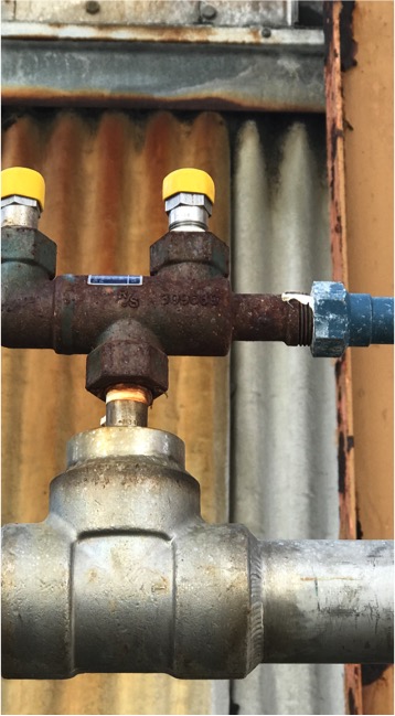
These are outdoor Hydrostats sitting atop a 3-way valve with their rain caps in place. This arrangement allows for one of the hydrostats to be replaced without having to shut down and evacuate that section of pipe in the continuous process. |
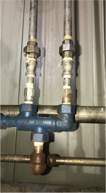
This is the same design, but inside. Here we can see the liquid NH3 line is run along the wall so the hydrostats can be vented outdoors (e.g “safe location”). |