
First I want to thank my Pittsburg friends for another great visit and for being my “think-tank” of world-class engineers and chemists. I always leave smarter and happier after my time with these folks. And with all my visits I always come away with great real-world examples of how process safety is supposed to be done! For years I have been harping on using a “tell-tale gauge” in dual relief systems (e.g. a rupture disc between the pressure vessel and the relief valve). When I teach my pressure vessel and relief RAGAGEP courses I always refer to my favorite redneck movie “Days of Thunder”. There was this scene that reminded me of my tell-tale gauges…
Cole (Tom Cruise) returns to racing after a bad wreck and in his first race back the engine in his race car blows up. He pulls into the pits and his pit chief “Harry” (Robert Duvall) asks him what happened and Cole mumbles something about not being a mechanic and for him to figure it out as he walks away. Harry leans into the car and hits a button on the Tach and it shows just how high the RPMs got… It turns out Cole blew up his engine because he was scared to be racing again. Corny as heck, but that little orange needle on the tach gauge was a “suitable telltale indicator” even though the engine was not running at the time.
All throughout my career, I had processes that were corrosive and we always had a Rupture Disc (RD) below the Relief Valve (RV) in order to protect the very expensive RV from being exposed to the corrosive atmosphere in the vessel. As I have written about many times, ASME Section VIII has some specific design requirements for these dual systems, one such requirement is that the space between the RD and RV be monitored to ensure the RD has not leaked and allowed pressure to enter the area and causing the RD to not burst at its set point. This telltale indicator must be manually checked at some frequency, but certainly as part of the start-up procedure and once per day/week/month (just depends on how disciplined the culture is at the facility).
But very early in my career, we had an incident where we were checking the “pressure gauges” once per day and all was well; until we had the incident. It turns out that we had the worst luck… the gauges were always checked when the “operators had the time” which essentially means the rounds were made between batch charges which meant the process was open to atmosphere and of course these gauges always read zero. One of the finest chemical engineers (an engineer’s engineer) fixed this problem with a very special gauge! And for nearly 30 years I have told everyone who had dual relief systems and would listen about these special gauges.
And my friends in Pittsburgh use these special gauges in their design:
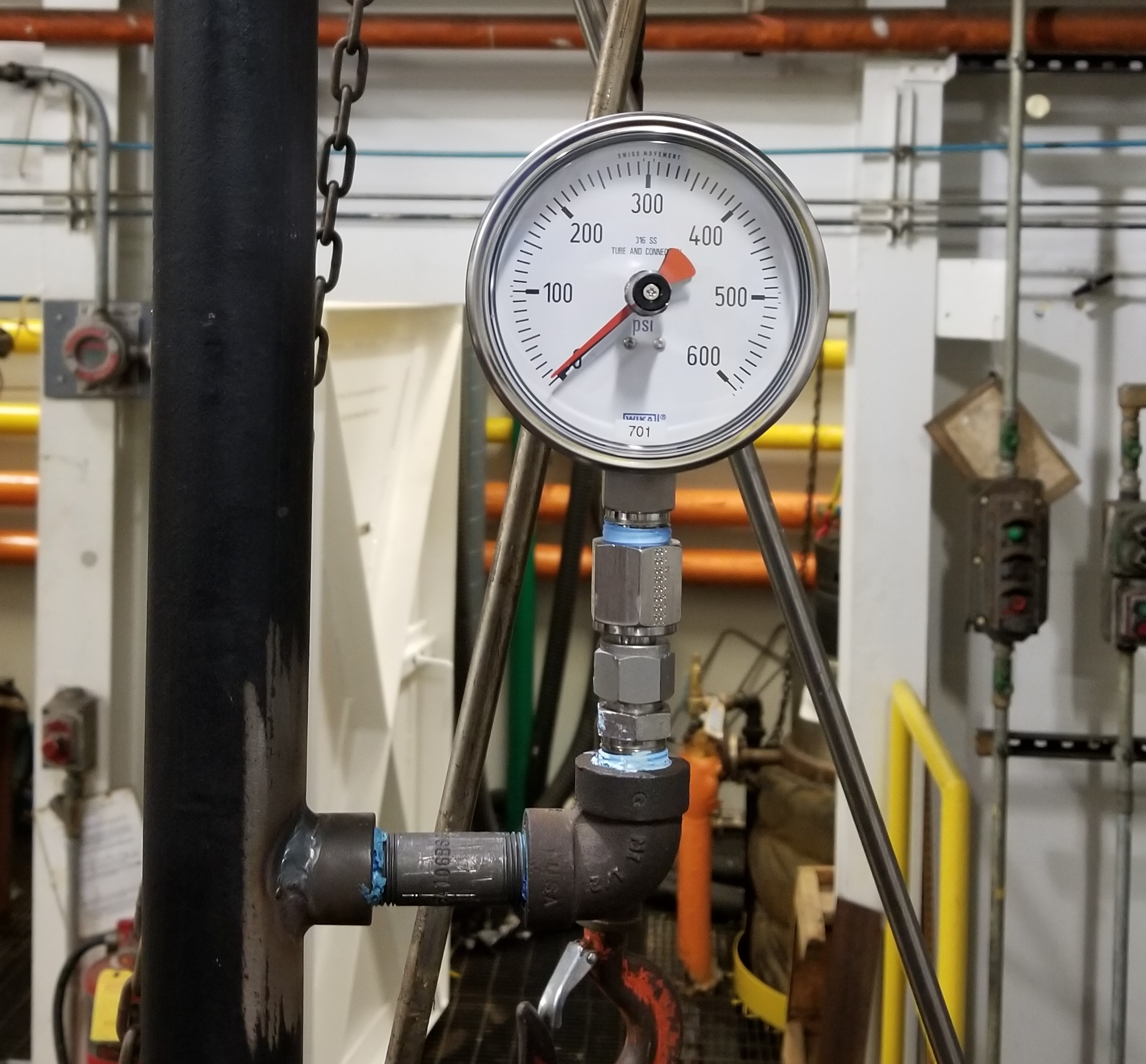
Here is a larger image of the picture of this special gauge:
It is the orange needle that is so special. It stays in place after the black needle has indicated a rise in pressure. Even though the black needle may return to zero, the orange needle will remain at the highest pressure the gauge had indicated. Now usually my “telltale” gauges had a much smaller range, but these gauges work for this process. Here is what we are trying to comply with:
UG-127 Nonreclosing Pressure Relief Devices
(a) Rupture Disk Devices
…
(3) Application of Rupture Disks
…
(-b) A rupture disk device may be installed BETWEEN A PRESSURE RELIEF VALVE AND THE VESSEL provided:
(-1) the combination of the pressure relief valve and the rupture disk device is ample in capacity to meet the requirements of UG-125(c);
(-2) the marked capacity of a pressure relief valve (nozzle type) when installed with a rupture disk device between the inlet of the valve and the vessel shall be multiplied by a factor of 0.90 of the rated relieving capacity of the valve alone, or alternatively, the capacity of such a combination shall be established in accordance with (-3) below;
(-3) the capacity of the combination of the rupture disk device and the pressure relief valve may be established in accordance with the appropriate paragraphs of UG-132;
(-4) the space between a rupture disk device and a pressure relief valve shall be provided with a pressure gage, a try cock, free vent, or suitable telltale indicator. This arrangement permits detection of disk rupture or leakage.
(-5) the opening provided through the rupture disk, after burst, is sufficient to permit a flow equal to the capacity of the valve [(-2) and (-3) above], AND there is NO CHANCE OF INTERFERENCE WITH PROPER FUNCTIONING OF THE VALVE; but in no case shall this area be less than the area of the inlet of the valve unless the capacity and functioning of the specific combination of rupture disk device and pressure relief valve have been established by test in accordance with UG-132.