This week I participated in an on-line discussion regarding a new “telltale indicator” that is being used in refrigeration processes. A really neat device that will indicate when an RV has lifted; however, I questioned its design and whether or not it could be considered an “obstruction” in the RV vent line. This device has a “paddle” type device that swings when moved by the pressure flowing through the device. The paddle is hinged on a bar that passes through the vent space.
CLICK HERE to see the patent drawing
This discussion got me thinking back to my days as a Safety and PSM Manager and working with some of the finest engineers in the petrochemical industry. One rule that I was taught very early in my career and told it was NEVER to be broken in any RV design was:
NEVER EVER allow any type of restriction in the system.
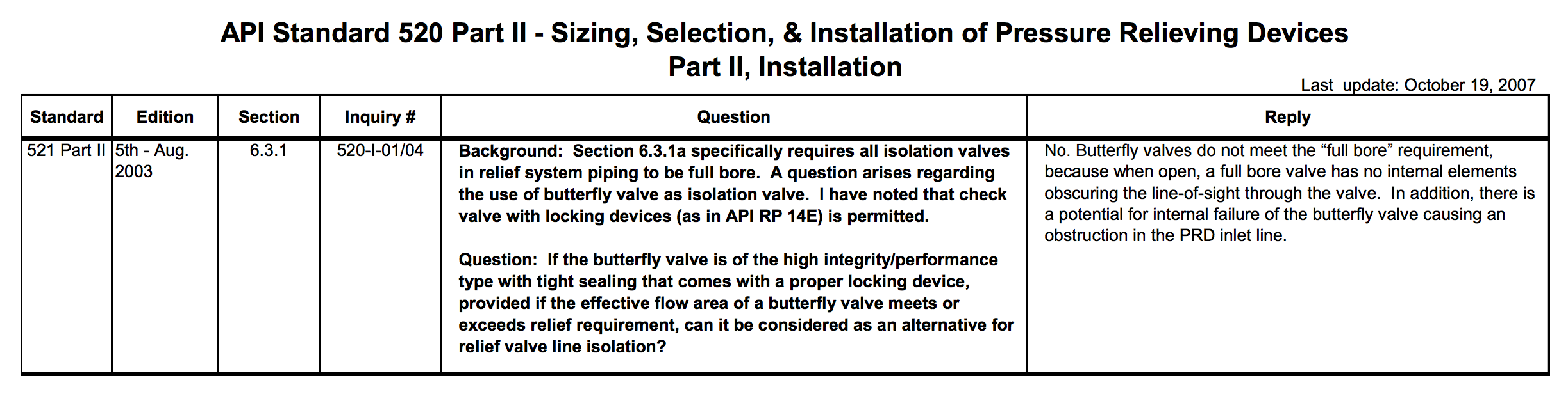
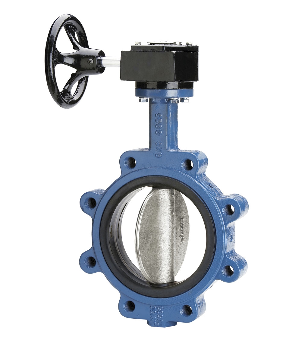
This rule was so strict, our internal engineering standards (as well as API 520) specified “full bore” valves for any isolation valve installed in the relief system. This meant that Butterfly Valves (as shown below) were prohibited to be used in this manner because even when they are fully open their internals present an obstruction. I always asked about using a larger valve to compensate for the internals being an obstruction and this was NOT permitted or good engineering practices.
This week I realized this info was not on SAFTENG.net and it is something we run into from time to time so I thought it may be help for some readers.
Now I know a lot of refrigeration facilities do not use API 520 as their RV RAGAGEP nor do many refrigeration processes have isolation valves (with a car seal program) in their vent lines/header(s) but here is what API 520 says about this topic:
6.3 ISOLATION VALVE REQUIREMENTS
In addition to previously noted inlet and outlet pressure drop restrictions, all isolation valves located in relief system piping shall meet the requirements provided in 6.3.1 and 6.3.2.
6.3.1 Inlet Isolation Valves
a. Valves shall be FULL BORE. ASME Section VIII Appendix M recommends the use of full area isolation (stop) valves. Mandatory paragraph UG-135 (b)(1), of ASME Section VIII, requires that the opening through all pipe and fittings between a pressure vessel and its pressure-relief valve shall have the area of the pressure-relief device inlet. It is therefore recommended that the minimum flow area in the isolation valve be equal to or greater than the inlet area of the pressure-relief valve. The minimum flow area of the isolation valve and the inlet area of the pressure relief valve can be obtained from the isolation valve manufacturer and the pressure-relief valve manufacturer.
b. Valves shall be suitable for the line service classification.
c. Valves shall have the CAPABILITY OF BEING LOCKED OR CAR SEALED OPEN.
d. When gate valves are used, they should be installed with stems oriented horizontally or, if this is not feasible, the stem could be oriented downward to a maximum of 45º from the horizontal to keep the gate from falling off and blocking the flow.
e. A BLEED VALVE SHOULD BE INSTALLED BETWEEN THE ISOLATION VALVE AND THE PRESSURE-RELIEF DEVICE to enable the system to be safely depressurized prior to performing maintenance. This bleed valve can also be used to prevent pressure build-up between the pressure-relief device and the closed outlet isolation valve.
f. Consideration should be given to using an interlocking system between the inlet and outlet isolation valves to assist with proper sequencing.
g. Consideration should be given to painting the isolation valve a special color or providing other identification.
When placing the pressure-relief device into service, it is recommended to gradually open the isolation valve. This ramping up of system pressure can help prevent unwanted opening of a valve seat due to the momentum of the fluid. The inlet valve must be open fully. Typical installations of isolation valves mounted at the inlet of pressure-relief devices are shown in Figures 11 through 13.
6.3.2 Outlet Isolation Valves
a. Valves shall be full bore. ASME Section VIII Appendix M recommends the use of full area isolation (stop) valves. To help minimize the built-up backpressure, it is recommended that the minimum flow area in the outlet isolation valve be equal to or greater than the outlet area of the pressure-relief valve. The minimum flow area of the outlet isolation valve and the outlet area of the pressure-relief valve can be obtained from the isolation valve manufacturer and the pressure-relief valve manufacturer respectively.
b. Valves shall be suitable for line service classification.
c. Valves shall have the capability of being locked or car sealed open. This outlet isolation shall never be closed while the vessel is in operation without using an inlet isolation valve that has Þrst been closed with the space between the inlet isolation valve and the pressure-relief valve adequately depressured.
d. A bleed valve should be installed between the outlet isolation valve and pressure-relief device to enable the system to be safely depressurized prior to performing maintenance. This bleed valve can also be used to prevent pressure build-up between the pressure-relief device and the closed outlet isolation valve.
e. Consideration should be given to using an interlocking system between the inlet and outlet isolation valves to assist with proper sequencing.
f. Consideration should be given to painting the isolation valve a special color or providing other identification.
When the outlet isolation valve is used in conjunction with an inlet isolation valve, upon commissioning the pressure relief device, the outlet isolation valve shall be opened fully prior to the inlet isolation valves. A typical installation of inlet and outlet isolation valves for pressure-relief valves are shown in Figure 10.
Here is a 2007 interpretation from API on the matter: