
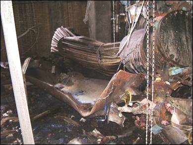
We do not see these types of failures often, but when we do, it can almost always be traced back to human error. Back in 2008, a tube-and-shell heat exchanger catastrophically failed when workers accidentally closed two different valves at two different times between the vessel and its relief valve. On June 10, 2008, operators closed an isolation valve between the heat exchanger shell (ammonia cooling side) and a relief valve to replace a burst rupture disk under the relief valve that provided over-pressure protection. Maintenance workers replaced the rupture disk that day; however, the closed isolation valve was not reopened.
On the morning of June 11, an operator closed a block valve, isolating the ammonia pressure control valve from the heat exchanger. The operator then connected a steam line to the process line to clean the piping. The steam flowed through the heat exchanger tubes, heated the liquid ammonia in the exchanger shell, and increased the pressure in the shell. The closed isolation and block valves prevented the increasing ammonia pressure from safely venting through either the ammonia pressure control valve or the rupture disk and relief valve. The pressure in the heat exchanger shell continued climbing until it violently ruptured at about 7:30 a.m.
A Car Seal program could have gone a long way in preventing this incident. A car seal program is simply a valve management program that contains:
- a list of safety-critical valves,
- their SAFE positions (could be either open or closed),
- a description of their location, and
- Some type of seal will prevent the valve from deviating from its SAFE position. This seal can be a plastic tie wrap, chain, or some metal banding. Some facilities even use color coding for their seals (e.g., green is for OPEN, and red is for CLOSED valves).
The program should also include your P&IDs; they should reflect which valves are in this program. Most P&IDs will use the designation CSO for Car Sealed Open and CSC for Car Seal Closed to show the valves in the program. Now comes the tricky part… the WORKERS!
The program (an administrative control) is only as good as the workers who use it and rely on it. Some facilities build the Car Seal deviation procedure into their Management of Change procedure, which means anytime a valve in the program wants to deviate from its SAFE position, a TEMPORARY MOC will be completed and this TEMP MOC will ALWAYS require a Pre-Start Up Safety Review (not because OSHA requires it for this temp MOC, but because we want to ensure this valve is returned to the safe position before returning the HHC/EHS) to that part of the process.
Some facilities will have a very basic board and tagging program where each sealed valve will be tagged with a weather-resistant tag that is in two parts. The tab at the end of the tag is the permission tab. This is the one that is removed and is signed by the appropriate personnel granting permission to deviate the valve. On the back of the tab, a matching number also appears on the part of the tag attached to the valve. The removed tab is hung on a Valve Deviation Board in PLAIN SIGHT in the control room, and the action should be entered into the shift logbook. Workers then return to the valve with the signatures and the tag hung on the board. The action communicated to ALL workers on shift (via radio announcement, but then all workers must acknowledge they received the transmission) will now require the valve to be deviated. The program will also require entry into either a paper logbook that is used to communicate shift change data or an electronic method, but it is CRITICAL that any and ALL valve deviations be communicated to ALL workers, including contractors whose work will involve any deviated valve.
Some facilities will even work valve deviations into their safe work permitting process to provide another layer of communication.
The next CRITICAL PATH is returning the valve(s) back to their safe position. This should be done as soon as possible. Some facilities will even have a policy that no car-sealed valve can remain out of its safe position for longer than a single shift. Putting the valve back into its safe position will require a new tag and a new seal, as well as another entry in the logbook and communication to the workers on shift about the valve’s new status.
The final step may be the most critical of all. The program needs to be audited to ensure its integrity. This auditing begins as part of a Pre-Start Up Safety Review to act as another assurance that the valves have been placed back into their SAFE position before the process is started. Some facilities will also include these critical valves in their Start-Up SOPs to ensure they are inspected BEFORE start-up. At some point, the facility will need to do a full audit of the program, including a physical inspection of each valve to ensure it is in its proper position, the tag is in place, and the seal integrity is intact.
In summary, there are many different variations of Car Seal programs, some very basic and some very advanced, but they all serve a critical role in process safety. The first place to consider using a car seal program is on ALL valves between a pressure vessel and its relief protection, or even downstream of relief valves. If your facility falls under OSHA’s PSM standard and EPA’s RMP rule, you could be cited for not having some form of a car-seal program if you have situations where this program would be a necessity (e.g., ASME Section VIII UG-135(d).
OSHA has recently included car-seal programs in its PSM audits. It made its first official appearance in the Refinery PSM Compliance Directive and is also making its way into the PSM Covered Chemical Facilities CPL.
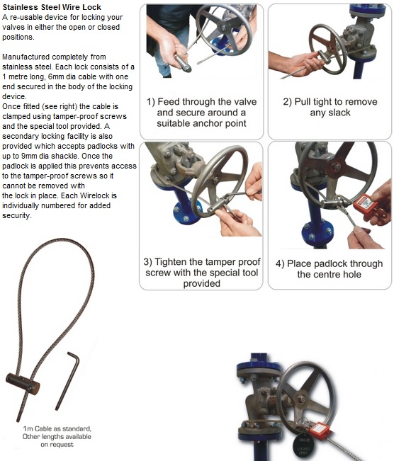
Example of what car-seal components would look like and work…
Many have asked for the portion of the ASME code and the National Board Inspection Code that states having an isolation valve before or after a PSV is allowed as long as they are Car Sealed OPENED (CSO) or in some other control system.
ASME Section VIII, UG-135 INSTALLATION
…
(d) There shall be no intervening stop valves between the vessel and its pressure relief device or devices, or between the pressure relief device or devices and the point of discharge, except:
(1) when these stop valves are so constructed or positively controlled that the closing of the maximum number of block valves possible at one time will not reduce the pressure relieving capacity provided by the unaffected pressure relief devices below the required relieving capacity; or
(2) under conditions set forth in Appendix M.
Appendix M-5 STOP VALVES LOCATED IN THE RELIEF PATH
M-5.1 General
(a) Stop valve(s) located within the relief path is NOT allowed EXCEPT as provided for in M-5.5, M-5.6, M-5.7, and M-5.8, and ONLY when specified by the user. The responsibilities of the user are summarized in M-5.3. The specific requirements in M-5.5, M-5.6, M-5.7, and M-5.8 are NOT intended to allow for normal operation above the maximum allowable working pressure.
(b) The pressure relief path SHALL BE DESIGNED such that the pressure in the equipment being protected does NOT exceed its maximum allowable working pressure before the pressure at the pressure relief device reaches its set pressure and the pressure does not exceed the limits of UG-125(c).
M-5.2 Definitions
administrative controls: procedures that, in combination with mechanical locking elements, are intended to ensure that personnel actions do not compromise the overpressure protection of the equipment. They include, as a minimum, Documented Operation and Maintenance Procedures, and Training of Operator and Maintenance Personnel in these procedures.
full area stop valve: a valve in which the flow area of the valve is equal to or larger than the inlet flow area of the pressure relief device.
management system: the collective application of administrative controls, valve operation controls, and valve failure controls, in accordance with the applicable requirements of this Division.
mechanical locking elements: elements that when installed on a stop valve, provide a physical barrier to the operation of the stop valve, such that the stop valve is not capable of being operated unless a deliberate action is taken to remove or disable the element. Such elements, when used in combination with adminstrative controls, ensure that the equipment overpressure protection is not compromised by personnel actions. Examples of mechanical locking elements include locks (with or without chains) on the stop valve handwheels, levers, or actuators, and plastic or metal straps (car seals) that are secured to the valve in such a way that the strap must be broken to operate the stop valve.
pressure relief path: consists of all equipment, pipe, fittings, and valves in the flow path between any protected equipment and its pressure relieving device, and between the pressure relieving device and the discharge point of the relieving stream. Stop valves within a pressure relief path include, but are not limited to, those located directly upstream and downstream of the Pressure Relief Device (PRD) that may be provided exclusively for PRD maintenance.
valve failure controls: measure taken in valve design, configuration, and/or orientation for the purpose of preventing an internal failure of a stop valve from closing and blocking the pressure relief path. An example of valve failure controls is the installation of gate valves with the valve stem oriented at or below the horizontal position.
valve operation controls: devices used to ensure that stop valves within the pressure relief path are in their proper (open/closed) position. They include the following:
- mechanical interlocks which are designed to prevent valve operations which could result in the blocking of a pressure relief path before an alternative pressure relief path is put into service.
- instrumented interlocks which function similar to mechanical interlocks, except that instrument permissives and/or overrides are used instead of mechanical linkages/devices to prevent valve positions that block the pressure relief path.
- three-way valves designed to prevent a flow path from being blocked without another flow path being simultaneously opened.
M-5.3 Responsibilities
The User has the RESPONSIBILITY TO ESTABLISH AND MAINTAIN A MANAGEMENT SYSTEM that ENSURES a vessel is NOT operated without overpressure protection. These responsibilities include, but are not limited to, the following:
- Deciding and specifying if the overpressure protection system will allow the use of stop valve(s) located in the relief path.
- Establishing the pressure relief philosophy and the administrative controls requirements.
- Establishing the required level of reliability, redundancy, and maintenance of instrumented interlocks, if used.
- Establishing procedures to ensure that the equipment is adequately protected against overpressure.
- Ensuring that authorization to operate identified valves is clear and that personnel are adequately trained for this task.
- Establishing management systems to ensure that administrative controls are effective.
- Establishing the analysis procedures and basis to be used in determining the potential levels of pressure if the stop valve(s) were closed.
- Ensuring that the analysis described in M-5.3(7) is conducted by personnel who are qualified and experienced with the analysis procedure.
- Ensuring that the other system components are acceptable for the potential levels of pressure established in M-5.3(g).
- Ensuring that the results of the analysis described in M-5.3(g) are documented and are reviewed and accepted in writing by the individual responsible for operation of the vessel and valves.
- Ensuring that the administrative controls are reviewed and accepted in writing by the individual responsible for operation of the vessel and valves.
NOTE: The procedures contained in ISA S-84, “Application of Safety Instrumented Systems for the Process Industries,” or IEC 61508, “Functional Safety of Electrical/Electronic/Programmable Electronic Safety-Related Systems,” may be used for this purpose and analysis.
M-5.4 Requirements of Procedures/Management System
(a) Procedures shall specify that valves requiring mechanical locking elements and/or valve operation controls and/or valve failure controls shall be documented and clearly identified as such.
(b) The Management System shall document the administrative controls (training and procedures), the valve controls, and the performance of the administrative controls in an auditable form for management review.
M-5.5 Stop Valves Provided in Systems for Which the Pressure Originates Exclusively From an Outside Source
A vessel or system [see UG-133(c)] for which the pressure originates from an outside source exclusively may have individual pressure relieving devices on each vessel, or connected to any point on the connecting piping, or on any one of the vessels to be protected. Under such an arrangement, there may be stop valve(s) between any vessel and the pressure relieving devices, and these stop valve(s) need not have any administrative controls, valve operation controls, or valve failure controls, provided that the stop valves also isolate the vessel from the source of pressure.
M-5.6 Stop Valve(s) Provided Upstream or Downstream of the Pressure Relief Device Exclusively for Maintenance of That Device
Full area stop valve(s) may be provided upstream and/or downstream of the pressure relieving device for the purpose of inspection, testing, and repair of the pressure relieving device or discharge header isolation, provided that, as a minimum, the following requirements are complied with:
- Administrative controls are provided to prevent unauthorized valve operation.
- Valves are provided with mechanical locking elements.
- Valve failure controls are provided to prevent accidental valve closure due to mechanical failure.
- Procedures are in place to provide pressure relief protection during the time when the system is isolated from its pressure relief path. These procedures shall ensure that when the system is isolated from its pressure relief path, an authorized person shall continuously monitor the pressure conditions of the vessel and shall be capable of responding promptly with documented, pre-defined actions, either stopping the source of overpressure or opening alternative means of pressure relief. This authorized person shall be dedicated to this task and shall have no other duties when performing this task.
- The system shall be isolated from its pressure relief path only for the time required to test, repair, and or replace the pressure relief device.
M-5.7 Stop Valve(s) Provided in the Pressure Relief Path Where There Is Normally Process Flow
Stop valve(s), excluding remotely operated valves, may be provided in the relief path where there is normally a process flow, provided the requirements in M-5.7(a) and (b), as a minimum, are complied with. These requirements are based on the potential overpressure scenarios involving accidental closure of a single stop valve within the relief path [see M-5.3(g)]. The accidental closure of these stop valve(s) in the pressure relief system need not be considered in setting the design pressure per UG-21.
(a) The flow resistance of the valve in the full open position does not reduce the relieving capacity below that required by the rules of this Division.
(b) The closure of the valve will be readily apparent to the operators such that corrective action, in accordance with documented operating procedures, is required, and (1) if the pressure due to closure of the valve can not exceed 116% of MAWP, then no administrative controls, mechanical locking elements, valve operation controls, or valve failure controls are required, or (2) if the pressure due to closure of the valve can not exceed the following:
- the documented test pressure, multiplied by the ratio of the stress value at the design temperature to the stress value at the test temperature, or
- if the test pressure is calculated per UG-99(c) in addition to the ratio in M-5.7(b)(2)(a), the test pressure shall also be multiplied by the ratio of the nominal thickness minus the corrosion allowance to the nominal thickness then, as a minimum, administrative controls and mechanical locking elements are required, or
- if the pressure due to closure of the valve could exceed the pressure in M-5.7(b)(2), then the user shall either
-
- eliminate the stop valve, or
- apply administrative controls, mechanical locking elements, valve failure controls, and valve operation controls, or
- provide a pressure relief device to protect the equipment that could be overpressured due to closure of the stop valve
M-5.8 Stop Valves Provided in the Relief Path of Equipment Where There Is Normally Process Flow and Where Fire Is the Only Potential Source of Overpressure
Full area stop valve(s) located in the relief path of equipment where there is normally process flow and where fire is the only potential source of overpressure do not require physical elements such as locks or car seals, valve operation controls, or valve failure controls provided the user has documented operating procedures requiring that equipment isolated from its pressure relief path is depressured and free of liquids.
NBIC and Car Seals
4.5.6 INSTALLATION AND DISCHARGE PIPING REQUIREMENTS
a) The opening through all pipe and fittings between a pressure vessel and its pressure relief device shall have at least the area of the pressure relief device inlet. The characteristics of this upstream system shall be such that the pressure drop will not reduce the relieving capacity below that required or adversely affect the proper operation of the pressure relief device. When a discharge pipe is used, the size shall be such that any pressure that may exist or develop will not reduce the relieving capacity below that required or adversely affect the proper operation of the pressure relief device. It shall be as short and straight as possible and arranged to avoid undue stress on the pressure relief device.
b) A non-reclosing device installed between a pressure vessel and a pressure relief valve shall meet the requirements of 4.5.6 a).
c) The opening in the pressure vessel wall shall be designed to provide unobstructed flow between the vessel and its pressure relief device.
d) When two or more required pressure relief devices are placed on one connection, the inlet cross-sectional area of this connection shall be sized either to avoid restricting flow to the pressure relief devices or made at least equal to the combined inlet areas of the pressure relief devices connected to it. The flow characteristics of the upstream system shall satisfy the requirements of NBIC Part 1, 4.5.6 a).
e) There shall be no intervening stop valves between the vessel and its pressure relief device(s), or between the pressure relief device(s) and the point of discharge, except under the following conditions:
1) When these stop valves are so constructed or positively controlled that the closing of the maximum number of block valves at one time will not reduce the pressure relieving capacity below the required relieving capacity; or,
2) Upon specific acceptance of the Jurisdiction, when necessary for the continuous operation of processing equipment of such a complex nature that shutdown of any part is not feasible, a full area stop valve between a pressure vessel and its pressure relief device should be provided for inspection and repair purposes only. This stop valve shall be arranged so that it can be locked or sealed open, and it shall not be closed except by an authorized person who shall remain stationed there during that period of operation while the valve remains closed. The valve shall be locked or sealed in the open position before the authorized person leaves the station.
3) A full area stop valve should also be placed on the discharge side of a pressure relief device when its discharge is connected to a common header for pressure relief devices to prevent discharges from these other devices from flowing back to the first device during inspection and repair. This stop valve shall be arranged so that it can be locked or sealed open, and it shall not be closed except by an authorized person who shall remain stationed there during that period of operation while the valve remains closed. The valve shall be locked and sealed in the open position before the authorized person leaves the station. This valve shall only be used when a stop valve on the inlet side of the pressure relief device is first closed.
5.3.6 INLET AND DISCHARGE PIPING REQUIREMENTS
a) The opening through all pipes and fittings between a piping system and its pressure relief device shall have at least the area of the pressure relief device inlet. The characteristics of this upstream system shall be such that the pressure drop will not reduce the relieving capacity below that required or adversely affect the operation of the pressure relief device.
b) A non-reclosing device installed between a piping system and a pressure relief valve shall meet the requirements of NBIC Part 1, 5.3.6 a).
c) The opening in the pipe shall be designed to provide unobstructed flow between the pipe and its pressure relief device.
d) When two or more required pressure relief devices are placed on the connection, the inlet cross-sectional area of this connection shall be sized either to avoid restricting flow to the pressure relief devices or made at least equal to the combined inlet areas of the pressure relief devices connected to it. The flow characteristics of the upstream system shall satisfy the requirements of NBIC Part 1, 5.3.6 a).
e) There shall be no intervening stop valves between the piping system and its pressure relief device(s), or between the pressure relief device(s) and the point of discharge except under the following conditions:
1) When these stop valves are so constructed or positively controlled that the closing of the maximum number of block valves at one time will not reduce the pressure relieving capacity below the required relieving capacity;
2) Upon specific acceptance of the Jurisdiction, when necessary for the continuous operation of processing equipment of such a complex nature that shutdown of any part is not feasible, a full area stop valve between a piping system and its pressure relief device should be provided for inspection and repair purposes only. This stop valve shall be arranged so that it can be locked or sealed open and it shall not be closed except by an authorized person who shall remain stationed there during that period of operation while the valve remains closed. The valve shall be locked or sealed in the open position before the authorized person leaves the station;
3) A full area stop valve may be placed on the discharge side of a pressure relief device when its discharge is connected to a common header for pressure relief devices to prevent discharges from these other devices from flowing back to the first device during inspection and repair. This stop valve shall be arranged so that it can be locked or sealed open, and it shall not be closed except by an authorized person who shall remain stationed there during that period of operation while the valve remains closed. The valve shall be locked or sealed in the open position before the authorized person leaves the station. This valve shall only be used when a stop valve on the inlet side of
the pressure relief device is first closed; or
4) A piping system where the pressure originates from an outside source should have a stop valve between the system and the pressure relief device, and this valve need not be sealed open, provided it also closes off that vessel from the source of pressure.
CLICK HERE for actual OSHA citations related to this topic.