
2/4/2015 UPDATE
After many lengthy discussions with engineers and inspectors I have come to the conclusion that although this practice may be permitted by code, albeit by a five-word phrase in an interpretation, most engineers stated they would NOT use a dual stamped vessel unless it was careful analyzed via a PHA or detailed engineering review. All those who I have communicated with said they would just get a vessel rated for the -50 and a higher pressure than 85 psi. But in all these discussions I and my team kept coming back to the Process Safety Management perspective… how would a facility document and be able to show OSHA/EPA that their pressure vessels…
1910.119(d)(3)(ii) The employer shall document that equipment complies with recognized and generally accepted good engineering practices.
It is an easy find for a knowledgeable auditor asking about vessels operating below the normal range of -20F when auditing a process that could have operating conditions below -20F. We see this in refrigeration and petrochemical processes where the materials have very low boiling points. If a vessel is, in fact, operating at temperatures lower than the -20F norm for carbon steel vessel, ask the following questions:
- What is the documented safe lower temperature listed in the PSI and SOPs?
- What does the relief system design basis state about operating the vessel in the lower ranges (i.e. -20 to -50) and having an RV set at 250 psi? Most auditors will take the basic approach of RV design and ask why the RV is set higher than the prescribed MAWP at the temperatures the vessel is operating at.
- Are there any safety systems involved in preventing vessels MDMT from being exceeded via process upset or operator error?
- If yes, are these listed in the PSI?
- Were these failures considered in the PHA?
- Are they listed in the applicable SOPs?
- If they are in the SOPs, do the SOPs contain steps to correct/avoid this deviation?
So if a facility is using dual stamped vessels, is it documented in their engineering design review and analysis of consequence of engineering failures (refer to 1910.119(d)(2)(i)(E)) as to how these vessels and why these vessels carry a “dual stamp”? This engineering review should document that consideration was given to the following conditions:
- the lowest operating temperature,
- operational upsets,
- autorefrigeration,(Linked to a great article from the NBBI on autorefrigeration)
- atmospheric temperature, and
- any other sources of cooling
One thing I learned via asking this question is that brittle fracture failure ALMOST ALWAYS occurs in a “transient state”, meaning that the vessel is either heating up or cooling down and in the last 30 years “most” (NOT ALL) process vessels that failed due to brittle fracture failure did so during start-up or during their hydrostatic testing as part of maintenance. Investigation reports shared with me (sorry I can not share them with you) pointed to the lack of proper start-up procedures (as well as operator ignorance of brittle fracture failure) and lack of proper hydrostatic testing maintenance procedures. Seems using too warm of water on a vessel that was just removed from cold service or introducing cold feedstock into a vessel that was allowed to warm up are critical points in the start-up and maintenance of these vessel(s) with really low MDMTs. Not one person I surveyed could recall a vessel failing because it was operating at too low of a temperature with an RV set too high. Having a catastrophic failure during hydro can be fatal as in the propane tank failure I posted years ago so it is nothing to take lightly, but it would not result in a release of the process hazardous material(s). A catastrophic failure during start-up very well could cause your “worst case” scenario to come true.
I have learned a lot from this journey and I still have questions that some have promised me answers to. And when I get these answers, I will share them with you. And speaking of the compliance aspect, we really should have our ducks in a row so as to explain with sound engineering how these vessels were safely designed and how they are being safely operated and safely maintained.
Bryan
2/1/2015 UPDATE
I have received responses from 19 of my 26 inquiries regarding this design question. I even posted the question on an engineering forum so as to get input from people not familiar with me. ALL of the 19 responses were either from engineers holding a PE credential or were an Authorized Inspector; I can not attest to the responses on the engineering forum. All those who responded stated they would NOT operate a pressure vessel above its MAWP and all stated that when operating in the range of -20F to -50F the MAWP would be 85 psi and therefore the RV would be set no higher than 85 psi.
However, a couple of my close engineering friends who always help me out did mention an ASME Interpretation that some may use to operate a vessel differently and I will share that interpretation. The answer to question #4 seems to permit the RV to be set at the higher MAWP, but my friends tell me that we have to refer to UG-20(b) for certainty and I posted UG-20(b), which does not actually answer question #4. A lot of great engineers are still wondering. I have yet to receive anything official from ASME or NBBI, so, for now, this ASME Interpretation is the best basis for having an RV set higher than the MAWP when there are multiple MAWP/MDMTs.
I have highlighted in red the specific question and answer. ALSO, be aware of ASME’s disclaimer on using these “interpretations”…
NOTE: THESE INTERPRETATIONS ARE FOR ASME COMMITTEE USE ONLY. THEY ARE NOT TO BE DUPLICATED OR USED FOR OTHER THAN ASME COMMITTEE BUSINESS.
In other words, the material below is NOT for use outside of the ASME committee(s)
Interpretation: VIII-1-01-23
Subject: Section VIII, Division 1 (1998 Edition, 1999 Addenda); UG-20(b), UG-99(b), UG-100(b), and UG-116(a)(3) and (a)(4)
Date Issued: January 8, 2001
File: BC00-084
Question (1): An MAWP and MDMT of a vessel are initially established using the rules of Section VIII, Division 1, Subsequently the rules of UCS-66(b)(1) are used to establish a second MDMT that is colder than the initial MDMT at a coincident MAWP that is lower than the initial MAWP. Based on footnote 37 in UG-116, may both the initial and second MAWP’s and MDMT’s be stamped on the nameplate?
Reply (1): Yes.
Question (2): If multiple MDMTs are selected to be shown on the nameplate or stamping, must each coincident pressure is shown on the nameplate be identified as “MAWP” per UG-116(b)(4)?
Reply (2): Yes.
Question (3): If multiple MAWP’s are shown on the nameplates or stamping, which MAWP is used to comply with the minimum hydrostatic test requirements of UG-99?
Reply (3): The MAWP that, after applying the mandatory stress ratio (see UG-99 and UG-l00), results in the highest test pressure.
Question (4): If multiple MAWP’s are shown on the nameplate or stamping, which MAWP is used to comply with the pressure relief device requirements of UG-125 through UG-137?
Reply (4): The largest value; see UG-20(b).
Question (5): In the cases where multiple MAPW’s are shown on the nameplate or stamping, requiring that the pressure relieving device(s) be set based on the largest value of MAWP, are Code rules available for the administrative controls associated with the lower MAWP(s)?
Reply (5): No.
Source: https://cstools.asme.org/csconnect/CommitteePages.cfm?Committee=N20110000&Action=863
Click Here to Download Division 1 (Volume 1-63) (645KB)
1/19/2015 UPDATE
I am pleased with the discussion this posting has generated. As with many of my posts, it is loved by some and hated by some. For those who wish to call me stupid, dumb, dangerous, etc. I am still awaiting your response with how your facility is complying with your chosen RAGAGEP for your Relief Valve Design Basis. As I stated in all my responses, educate me and I will share “the right information” with my readers. I have had numerous discussions with many talented and experienced engineers who have decades of experiences in managing and inspecting pressure vessels and so far NOT ONE has stated they would permit this type of design. I have received numerous e-mails from a particular industry laying claim that this is an “industry practice” that neither OSHA or EPA have ever cited or taken issue with. All I can say is that an “industry practice” is what killed six (6) workers, one of which was one of the FINEST SAFETY PROFESSIONALS to walk among men – RIP Chris!) at the Kleen Energy Power Plant. It was “industry practice” to use natural gas to “blow down” new piping in order to clean it out after installation.
“Turbine manufacturers typically require power plants to meet fuel piping cleanliness standards as part of the turbine warranty requirements. Cleanliness criteria are usually met by demonstrating that the number of impact marks made on a target placed in the flow of the natural gas blow by debris exiting the piping falls below pre-determined limits and sizes.” (CSB Report)
Although some companies had quit using Natural Gas as their blow down media, it was still considered an “industry practice” to use Natural Gas. This after several earlier explosions/fires involving the practice. So when someone lays claim that it is an “industry practice” that to me is just a way of saying… “well they did it – so why can’t I”. And the argument that OSHA or EPA have not issued citations on this matter is in NO WAY making this a sound engineering practice or is in no way an unspoken endorsement by these agencies.
Here is a U-1 Form showing the “Dual Stamp”
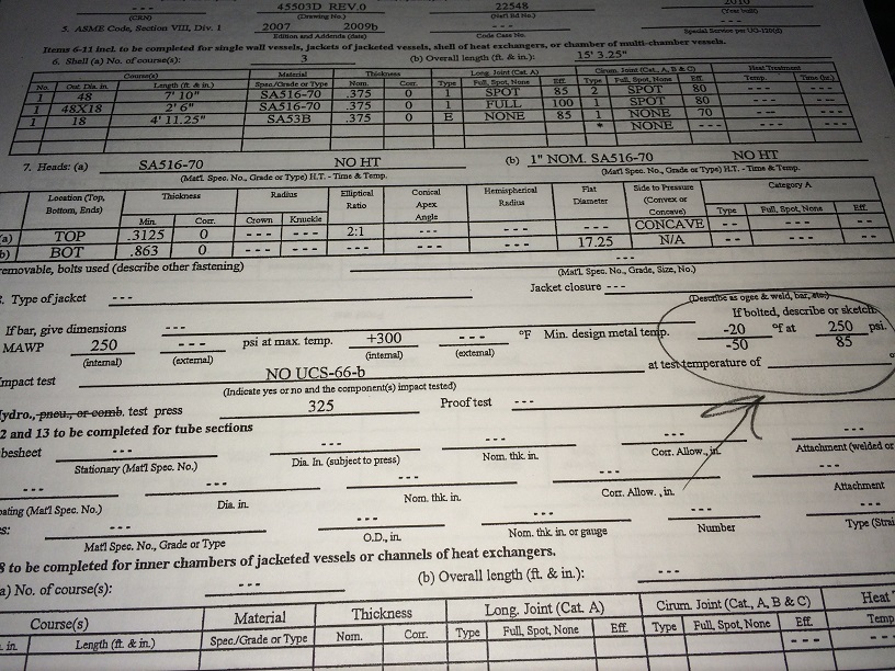
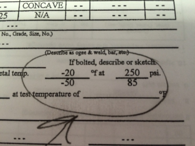
THIS IS NOT ENGINEERING or DESIGN ADVICE… merely asking how a facility can operate an ASME pressure vessel with a stamped MAWP with the RVs set higher than the MAWP for the process conditions. I am NOT challenging the practice of manufacturing pressure vessels and dual stamping them, which ASME Section VIII permits. I am questioning the practice in how these vessels are used within some processes.
The practice of fabricating pressures vessels that have different Maximum Allowable Working Pressure (MAWP(s) at different Minimum Design Metal Temperatures (MDMT) has been around for a while. Walk into any “pilot plant” or “Research and Development (R&D) Plant” and you will almost be certain to come across a pressure vessel with a “dual stamp”. These dual stamped vessels are necessary because of the varying conditions these vessels may see within a pilot plant or R&D type operation. However, in these types of operations, these vessels are outfitted with relief devices with set points that would NOT exceed the MAWP for the operating condition. By this, I mean that if one day the plant was using the vessel and it would see -60F temperature, the Relief Valves would be changed out to match the MAWP for this lower MDMT. The next week the vessel will be used at higher temps and thus the RV would be changed to one with a higher set point to go along with the higher MAWP. In some situations, we used three-way valves on an “RV tree” in which we could go back and forth with a mere changing of the 3-way valve position. But at NO TIME would we ever run a pressure vessel with an RV that had a set point higher than the “stamp” associated with the process conditions. This flies in the face of some practices we have been seeing more and more in some PSM/RMP covered processes.
In 2014 SAFTENG worked with several businesses and design/construction firms on the design and construction of processes and it seems that “dual stamping” has found its way to now being called an “industry accepted practice” within some industries – whatever that means! But these vessels are NOT being managed as I explained above. They are being installed with “dual stamped” nameplates for MDMTs of -20F and -60F seems to be the end of the Minimum Design Metal Temperature (MDMT) spectrum. This dual stamping is perfectly acceptable, but it is my opinion that the dual stamping provides flexibility to the owner/operator in how the vessel will be used within the process design. But this dual stamp does NOT permit the vessel to be used normally at the MDMT of -20F one day and then with the changing of a couple of process valves allow the vessel to be pulled down into ranges where it will see temps colder than -20F without first changing the RVs to match the “stamped” MAWP . Here are my concerns…
Strictly speaking CODE COMPLIANCE
UG-125 GENERAL
…
(1) It is the user’s or his/her designated agent’s responsibility to identify all potential overpressure scenarios and the method of overpressure protection used to mitigate each scenario.
(2) It is the responsibility of the user to ensure that the required overpressure protection system is properly installed prior to initial operation.
(3) If a pressure relief device(s) is to be installed, it is the responsibility of the user or his/her designated agent to size and select the pressure relief device(s) based on its intended service. Intended service considerations shall include, but not necessarily be limited to, the following:
(a) normal operating and upset conditions
(b) fluids
(c) fluid phases
…
(2) When a pressure vessel can be exposed to fire or other unexpected sources of external heat, the pressure relief device(s) shall be capable of preventing the pressure from rising more than 21% above the maximum allowable working pressure. Supplemental pressure relief devices shall be installed to protect against this source of excessive pressure if the pressure relief devices used to satisfy the capacity requirements of UG-125(c) and UG-125(c)(1) have insufficient capacity to provide the required protection. See Nonmandatory Appendix M, para. M-13 for cases where the metal temperature due to fire or other sources of external heat can cause vessel failure prior to reaching the MAWP.
…
UG-134 PRESSURE SETTINGS AND PERFORMANCE REQUIREMENTS
(a) When a single pressure relief device is used, the set pressure marked on the device shall not exceed the maximum allowable working pressure of the vessel. When the required capacity is provided in more than one pressure relief device, only one pressure relief device need be set at or below the maximum allowable working pressure, and the additional pressure relief devices may be set to open at higher pressures but in no case at a pressure higher than 105% of the maximum allowable working pressure, except as provided in (b) below.
(b) For pressure relief devices permitted in UG-125(c)(2) as protection against excessive pressure caused by exposure to fire or other sources of external heat, the device marked set pressure shall not exceed 110% of the maximum allowable working pressure of the vessel. If such a pressure relief device is used to meet the requirements of both UG-125(c) and UG-125(c)(2), the device marked set pressure shall not be over the maximum allowable working pressure.
So how does a facility document that their process relief design basis meets “Recognized and Generally Accepted Good Engineering Practices” when they are operating a vessel with a “stamped” MAWP of something like 85 psi and having relief valves set at 300 psi?
The arguments presented to me seem to always be… that when the vessel is operating at the -60F temperature that it will be under a vacuum and that there is no scenario in which the vessel would be at -60F and see a pressure greater than 85 psi… meaning that there is no need to have RV’s set at 85 psi.
Taking this back full circle to complying with the chosen RAGAGEP… I know of NO RAGAGEP that permits the RV to have a higher set point than the vessels stamped MAWP. And when it comes to “dual stamps”, we MUST respect BOTH set points with the proper RV Design Basis and set points. Dual stamp vessels provide some flexibility for the vessel’s utilization within the process stream, but in my opinion, it does NOT permit the vessels operating conditions to be changed without changing the relief system to match its operating conditions.
NOTE Added on 1/16/2015:
The National Board of Boiler and Pressure Vessel Inspectors Fall publication, The Bulletin, which is the Technical Journal of the National Board of Boiler and Pressure Vessel Inspector contained an EXCELLENT article by John Hoh, Senior Staff Engineer at the NBBI on Minimum Design Metal Temperature (MDMT) in regards to the potential to cause catastrophic failure of a pressure vessel from embrittlement. His article makes some very valid points in regards to my attempt at explaining this issue:
-
“Some materials, including some common carbon steels, do not behave well at cold temperatures and may experience brittle fracture while under stress. That is an over-simplified explanation but it helps summarize what we want to avoid – a catastrophic failure.”
-
“We would like to believe vessels are designed with the operating environment in mind, but there are many “stock” vessels (a common design for a common use – an air receiver is an example) operating in a wide range of environmental conditions. Consider the typical air receiver: the MDMT is usually -20°F. Some owners may locate the air receiver and its attached compressor outside under a shed roof to keep the noise out of the enclosed shop. During the winter, some regions can easily dip below -20°F ambient temperature. If the metal temperature of the air receiver measures below that -20°F stamped on the nameplate, it must not be pressurized.”
CLICK HERE for his full article. Although the article does not call out process vessels operating in a chemical process, the temperature of the shell of that vessel does not care if the cooling is from within or from mother-nature.
More from ASME Section VII, Division 1…
UG-20 DESIGN TEMPERATURE
(a) Maximum. Except as required in UW-2(d)(3), the maximum temperature used in the design shall be not less than the mean metal temperature (through the thickness) expected under operating conditions for the part considered (see 3-2). If necessary, the metal temperature shall be determined by computation or by measurement from equipment in service under equivalent operating conditions. See also U-2(a).
(b) Minimum. The minimum metal temperature used in the design shall be the lowest expected in service except when lower temperatures are permitted by the rules of this Division (see UCS-66, UCS-160, and footnote 37, UG-116). The minimum mean metal temperature shall be determined by the principles described in (a) above. Consideration shall include the lowest operating temperature, operational upsets, autorefrigeration, atmospheric temperature, and any other sources of cooling [except as permitted in (f)(3) below for vessels meeting the requirements of (f) below]. The MDMT marked on the nameplate shall correspond to a coincident pressure equal to the MAWP. When there are multiple MAWP’s, the largest value shall be used to establish the MDMT marked on the nameplate. Additional MDMT’s corresponding with other MAWP’s may also be marked on the nameplate (see footnote 37)
37When a pressure vessel is expected to operate at more than one pressure and temperature condition, other values of maximum allowable working pressure with the coincident permissible temperature may be added as required. See UG-20(b).
UG-21 DESIGN PRESSURE
Each element of a pressure vessel shall be designed for at least the most severe condition of coincident pressure (including the coincident static head in the operating position) and temperature expected in normal operation. For this condition, the maximum difference in pressure between the inside and outside of a vessel, or between any two chambers of a combination unit, shall be considered [see UG-98 and 3-2]. See also U-2(a).
UG-98 MAXIMUM ALLOWABLE WORKING PRESSURE
UG-98(a) The maximum allowable working pressure for a vessel is the maximum pressure permissible at the top of the vessel in its normal operating position at the designated coincident temperature specified for that pressure. It is the least of the values found for maximum allowable working pressure for any of the essential parts of the vessel by the principles given in (b) below and adjusted for any difference in the static head that may exist between the part considered and the top of the vessel. (See 3-2.)
UG-98(b) The maximum allowable working pressure for a vessel part is the maximum internal or external pressure, including the static head thereon, as determined by the rules and formulas in this Division, together with the effect of any combination of loadings listed in UG-22 which are likely to occur, for the designated coincident temperature, excluding any metal thickness specified as corrosion allowance. See UG-25.
UG-98(c) Maximum allowable working pressure may be determined for more than one designated operating temperature, using for each temperature the applicable allowable stress value.