
FM Global, my absolute favorite source of RELIABLE and FREE safety information has published a new Data Sheet titled 7-13 Mechanical Refrigeration. This data sheet and hundreds more are available for FREE (after a very brief registration) to anyone. A truly MUST have for any safety professional working in an industrial environment! In their new Data Sheet, 7-13 Mechanical Refrigeration, FM Global shares some of their internal loss histories and events with us, of which I find helpful when trying to explain why the codes/standards have multiple layers of protection built into them, as well as some nice engineering suggestions that may come in handy for those looking to go above and beyond IIAR and OSHA/EPA requirements.
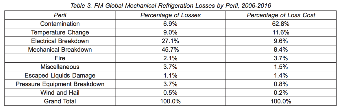
Table 3 describes the mechanical refrigeration losses experienced by FM Global clients in the period from January 2006 through June 2017. While representing a relatively small number of incidents, CONTAMINATION (e.g. ammonia getting into food areas) is the LOSS LEADER IN TERMS OF LOSS COST. All contamination incidents involved ammonia refrigeration systems where the leak either occurred in the refrigerated area or there was inadequate separation between the machinery room and refrigerated area, allowing ammonia gas to migrate to the refrigerated area. The causes of the ammonia releases included the following:
NOTE: this data is FREE when you register at FM Global and can download their data sheets. The content below, the notations, highlights, and explanations, are for SAFTENG members.
- Mechanical failure of a fan coil unit causing the fan blade to impact and rupture an ammonia line
- Ammonia line impacted by forklift
- Flange failure on an ammonia line
- Mechanical room fire resulted in ammonia release and migration into refrigerated area
- Compressor failure
- Operator error
#1 cause of losses BY FREQUENCY is MECHANICAL BREAKDOWN of equipment.
The most common equipment cited in mechanical breakdown was the compressor. Compressors, including maintenance and inspection, are covered by Data Sheet 7-95, Compressors.
#2 cause of losses BY FREQUENCY is ELECTRICAL BREAKDOWN of equipment.
Electrical breakdown was often related to electrical short circuits, arcing, or failure in controls such as control panels, temperature sensing devices, and compressor motors. These issues are addressed in other FM Global Property Loss Prevention Data Sheets. Several other electrical breakdown losses were associated with power outages.
Here is a break down of their losses and their causes from 2006 – 2016:
They also offer some more detailed analysis of several incidents they were involved with:
(NOTE: emphasis below was by me, NOT by FM Global)
Ammonia Contamination in Refrigerated Warehouse
An ammonia leak occurred at a 225,000 ft2 (21,000 m2) refrigerated storage facility consisting of nine separate refrigerated areas. A maintenance employee mistakenly removed a refrigerant drain valve on an evaporator unit, causing the release of ammonia. Ammonia detectors were ONLY installed in the machinery room and two of the nine refrigerated areas. The plant was NOT equipped with an emergency shutdown system for the refrigeration equipment. The refrigeration system was manually shut down and the plant evacuated. Ammonia vapors migrated from the area where the leak occurred to three additional refrigerated areas through open doorways in interior walls. Ammonia contamination mitigation efforts proceeded for approximately four days. In addition to the loss of product in storage, the BRASS SPRINKLERS in the affected areas were replaced due to the chemical reaction between ammonia and brass.
Ammonia Explosion in Machinery Room at a Frozen Food Production Facility
An ammonia release and subsequent explosion occurred at a 170,000 ft2 (16,000 m2) frozen food production facility. The machinery room was located within the envelope of the building being served with two exterior walls. The two interior walls separating the machinery room from the main plant area were 8 in. (200 mm) concrete block. The machinery room was equipped with ammonia detectors, but the detectors were NOT arranged to alarm to a constantly-attended location. At the time of the release, the ammonia refrigeration system was shut down in preparation for the installation of a new blast freezer. At approximately 2:00 am, a security guard noticed a high-pitch noise coming from the machinery room, likely the ammonia detector alarm. The guard determined that there was an ammonia leak in the machinery room and contacted appropriate personnel and first responders. An EXPLOSION OCCURRED IN THE MACHINERY ROOM at approximately 2:45 a.m. with no fire following. The explosion resulted in:
- damage to the roof requiring complete replacement,
- complete destruction of the two interior concrete block walls,
- partial destruction of a second interior wall located across an interior corridor from the machinery room walls, and
- damage to the exterior metal panel walls
Vessels and compressors were lightly damaged and were returned to service after repair. The cause of the release was found to be an INADEQUATELY-SUPPORTED PIPE ELBOW BETWEEN A RECEIVER AND LIQUID RETURN UNIT THAT FAILED AT A THREADED CONNECTION DUE TO TORSIONAL STRESS. Production at the facility ceased for approximately TWO WEEKS for mitigation and repair.
Here are a couple of other suggestions they have incorporated into this data sheet:
- Provide an emergency shutdown system arranged to AUTOMATICALLY CLOSE ALL LIQUID ISOLATION VALVES UPSTREAM OF THE ASSOCIATED ACCUMULATORS AND/OR RECEIVERS AND EVAPORATOR COIL UNITS. When a leak is detected in the refrigerated area, the liquid isolation valves should close but the COMPRESSOR SHOULD CONTINUE to operate so the ammonia returns to the machinery room and the volume leaked into the refrigerated space is minimized.
- PLEASE NOTE this in line with our recommendations to clients who make blanket generalities in their Operating Procedures, such as “In the event of a Leak activate the emergency shutdown”. Activating the ESD system for any leak – anywhere on the process could make the leak MUCH WORSE, than if the compressor was allowed to run and keep the system under a vacuum and pull a large amount of ammonia back to the secured part of the system.
- Have refrigerant detectors calibrated by qualified personnel at least quarterly or in accordance with manufacturer’s instructions, whichever is shorter, for the FIRST YEAR OF SERVICE. The calibration frequency can be extended to 6 months or in accordance with manufacturer’s instructions, whichever is shorter, following the first year of service if previous calibrations were within normal adjustment ranges identified by the manufacturer.
- Most NH3 refrigeration systems rely heavily on NH3 detectors in areas that may not be occupied at all times. As demonstrated in the incidents above, both incidents involved issues with the detector system design/maintenance, hence why FM Global is placing an emphasis on the detector’s calibration.
-
2.4.3.4 Locate all critical valves that can be used to isolate the flow of liquid refrigerant and all hot gas to the plant so as to be readily accessible from the floor level (direct or chain) or from access platforms. (HUMAN FACTORS)
-
Install shut-off and/or isolation valves at locations to minimize the amount of refrigerant released and facilitate draining of refrigerant when systems are shut down following an emergency.
-
The actual number of shut-off/isolation valves will vary depending on the piping system size, complexity, and the potential exposure created by a release.
-
Welded or flanged valves are preferred for all sizes; however, threaded valve bodies are acceptable for sizes 1.00 in. (2.54 cm) and smaller.
-
Label critical valves by attaching permanent, easily-readable tags.
-
Post a system drawing outside of the machinery room(s) and refrigerated spaces indicating the location of all critical valves. Identify the type(s) of refrigerant(s) in the system(s) on the drawing.
-