
It is the year 2021 and OSHA’s Process Safety Management standard will be 29 years old this May. Most processing facilities have come a long way in improving their process safety, but most still lack a comprehensive WRITTEN management program for their Safety Controls, Alarms, and Interlocks (SCAI). These safety instrumented systems (SIS) play a critical role in almost all of the PSM/RMP covered processes operating today, yet when asked to explain how these systems were chosen, designed, built, and maintained the answers can be quite worrisome. Like all of our process safety management systems, we need them to be documented so that if the current PSM/RMP team wins a lottery and fails to show up to work tomorrow, management is not in the dark when it comes to these critical safety systems. In comes FM Global and their FREE Property Loss Prevention Data Sheets, specifically 7-45 Safety Controls, Alarms, and Interlocks (SCAI). This datasheet can be downloaded and easily revised to form your baseline WRITTEN management program for the Safety Controls, Alarms, and Interlocks (SCAI) already in place in our processes and any new ones that we may find a need for in the future. Heck, this data sheet can even be used for our non-processing equipment that has interlocks associated with them. Here are some HIGHLIGHTS that Global FM explains so well:
(some minor edits and emphasis by me)
SIS performs differently than basic process control systems (BPCS). They are dormant and are activated ONLY when the parameters established in the safety functions exceed the safety limits. SISs needs to be tested and maintained regularly to ensure the proper operation of the system when needed.
BPCS elements actively provide input/output, perform calculations, and have feedback loops. These systems must be flexible enough to allow frequent process changes.
INDEPENDENCE and PHYSICAL SEPARATION can be done for BPCS and SIS to PREVENT common cause failures, as shown in Figure 2, where the final element could be an on/off valve that is normally open to allow the flow control valve to regulate the process feed under normal operating conditions. In the event of an upset condition, the safety valve is commanded shut by the safety system, INDEPENDENT of what the control system is signaling to the flow control valve.
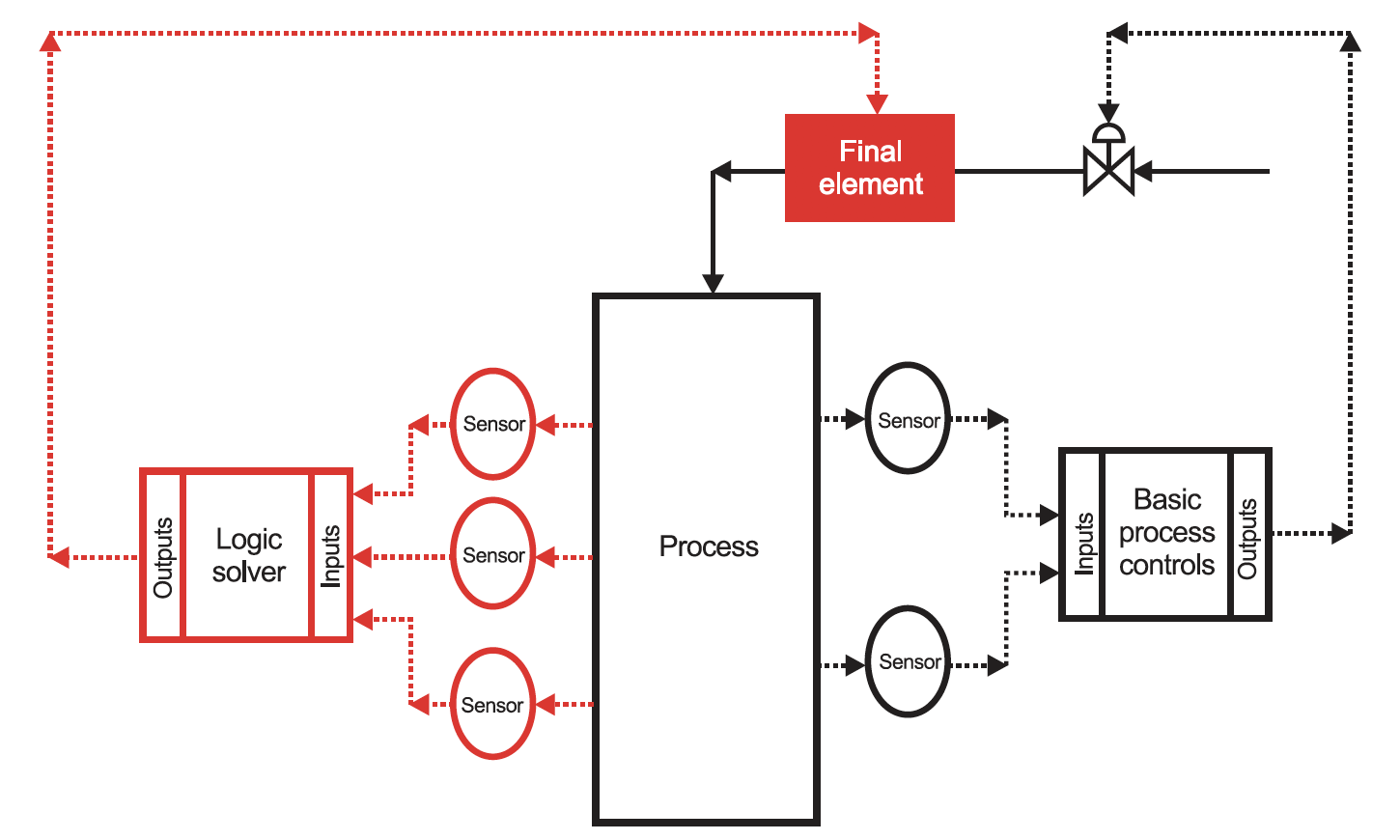
Fig. 2. Separated BPCS and SIS
Final elements are parts of the BPCS or SIS that implement the physical action necessary to achieve or maintain a safe state. Some examples include valves, switchgear, motor controllers, and alarms (visual and audible). However, there are cases in which the SIS is connected to the BPCS as shown in Figure 3 (a modern electronic overspeed system integrated into the overall control system of a turbine).
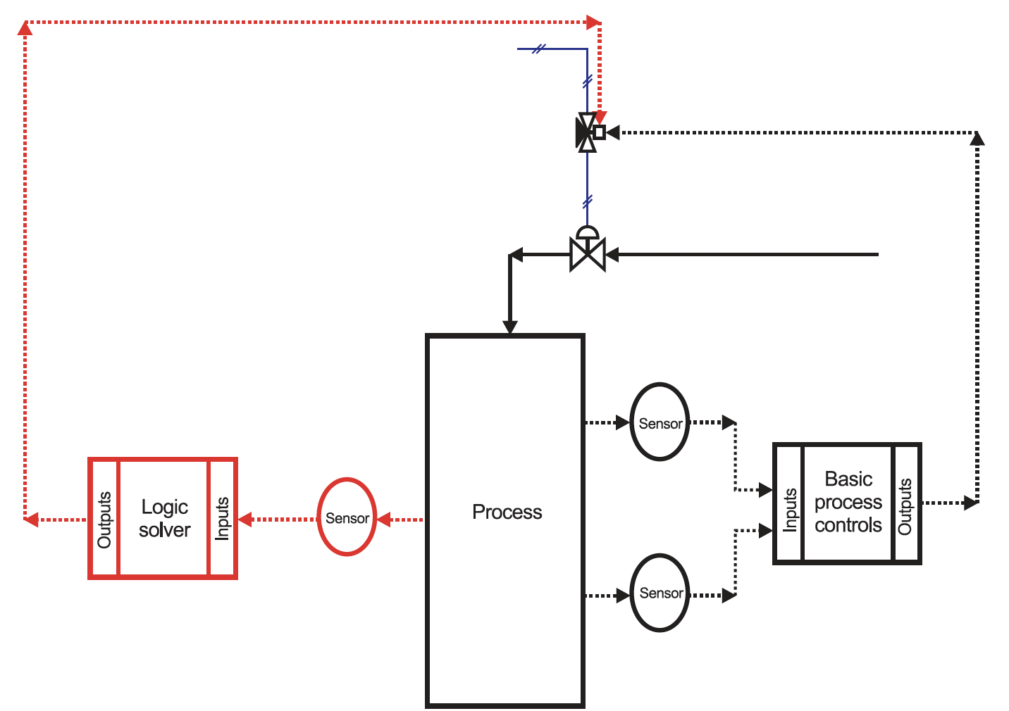
Fig. 3. Interconnected BPCS and SIS
It is important to note there are two independent functions:
- the control of the process (BPCS), and
- its safety
Process control systems ensure the quality and quantity of the product and frequently reduce the need/reliance on an operator to produce the product. The SIS activates when the BPCS fails to perform. A well-designed BPCS can significantly reduce the demands on the SIS and reduce the overall risk presented by the process.
SCAI’s are process safety safeguards, implemented with instrumentation and controls that are used to achieve or maintain a safe state for a process and that are required to reduce the risk(s) associated with a specific hazardous event. SCAI’s are the most common safeguards used to prevent abnormal operations from becoming a loss event. There are four basic types of SCAI:
- safety controls,
- safety alarms,
- safety interlocks, and
- safety instrumented systems (SIS)
SCAI can be implemented using BPCS or SIS equipment. IEC 61511 specifies that unless the BPCS equipment is designed and managed per IEC 61511, the SIS equipment MUST be independent and separate from the BPCS equipment to the extent that the safety integrity of the SIS is not compromised. Operating information can be exchanged but should NOT compromise the functional safety of the SIS. Devices of the SIS can also be used for functions of the BPCS if it can be demonstrated that a failure of the BPCS does NOT compromise the Safety Instrumented Functions (SIF) or the SIS.
Another major flaw we see most often is how these SISs are VALIDATED and at what FREQUENCY they are validated. FM does a nice job explaining this critical aspect of managing SISs:
Functional Testing
The main objective of SCAI functional testing is to VALIDATE THE RELIABILITY of ALL the elements in the system. Logic solvers, measurements, and final control elements are validated through a variable process manipulation in a simulating mode under various operating conditions, reflecting real operating conditions as accurately as possible, without actually driving the system to the demand conditions. The tests reveal undetected failure modes that would prevent any SCAI from properly functioning and generate proof that the system will operate accordingly to design specifications.
There are two primary types of testing:
- OFFLINE TESTING. The test is performed when the process is not operational. It covers a more comprehensive evaluation for newly installed equipment or after changes or modifications to the system has been made.
- ONLINE TESTING. The test is performed while the process is operational. It requires special safety considerations to prevent abnormal operational conditions during the testing process. In some cases, additional sensors, test taps, bypass, or isolation valves may be required.
Testing intervals are determined based on
- the SIL requirements,
- mode of operation (low or high demand),
- dangerous failure rates (detected and undetected),
- common cause failures (β-factors) and
- architecture type (redundancy).
The equations from IEC 61508-6:2010 Annex B, can be used to calculate the testing intervals of an SIS.
Procedures MUST be followed to ensure the quality and consistency of proof testing and to ensure adequate validation is performed after the replacement of any device.
If end-to-end testing is not possible, testing of each individual component can be made at different times. Items such as bypasses or overrides need to be handled under strict controls to ensure subsequent removal. Batteries, uninterruptible power supplies (UPS), generators, compressed-air tanks, and other emergency power supply to an SIS should be subject to routine ITM in order to ensure that the reliability of the SIF is maintained, as defined by a recognized standard or defined by the PHA and SIL analyses.
The last critical aspect that FM does such a great job of pointing out is the Manual Response Times (MRT). Automatic safety systems operation mode is preferred over the manual operation. However, when automatic mode is not possible or available, the manual response can be considered if operators are provided with adequate time to respond in an emergency. Figure 9 shows the elements that need to be considered when determining the manual response time (MRT).
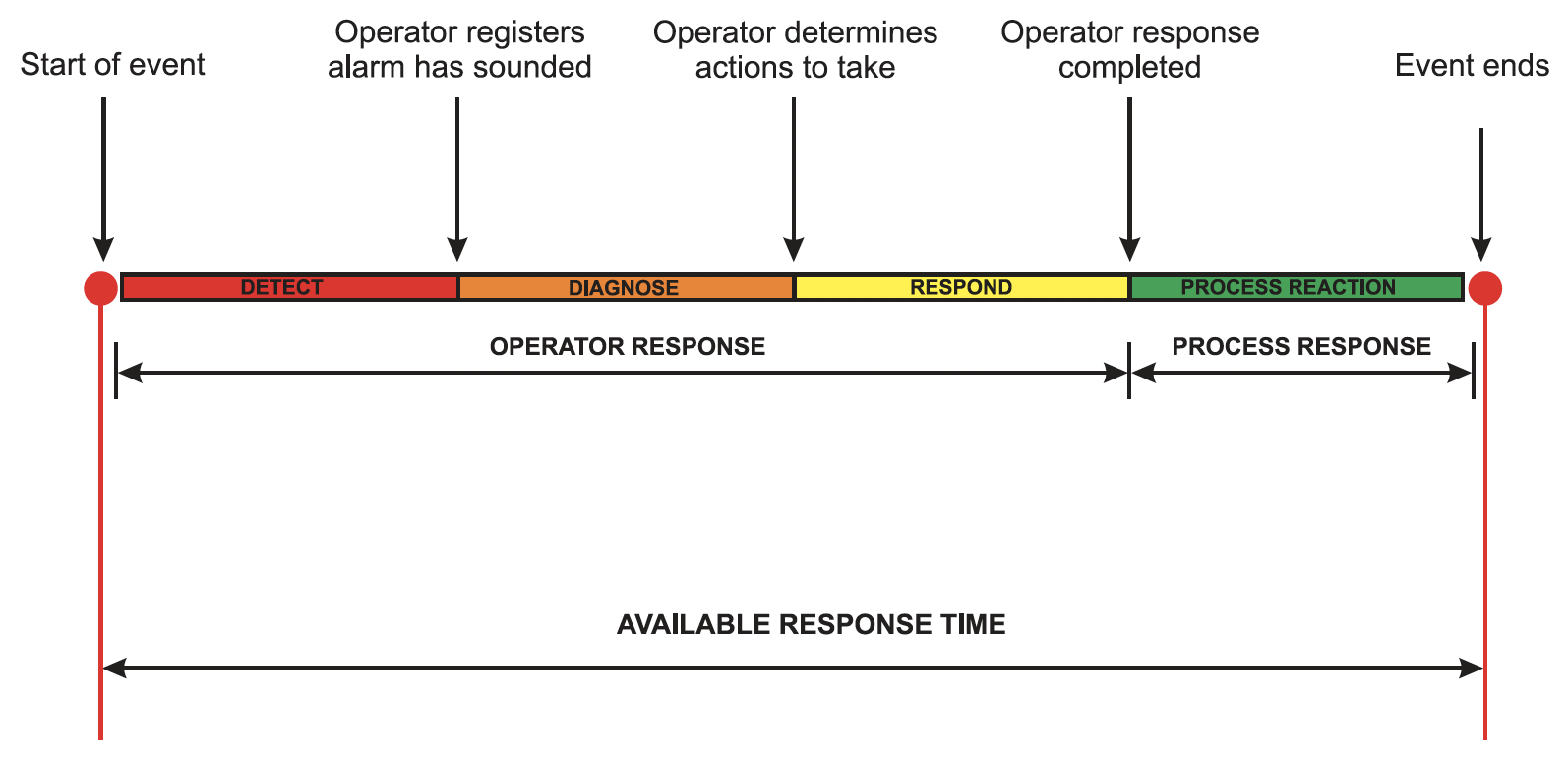
Fig. 9. Elements involved in determining manual response time (MRT)
As shown, the MRT is made up of the operator response time PLUS the process response time. The operator response time is made up of the sum of:
- the time needed to detect (and acknowledge) the alarm,
- plus the time the operator needs to diagnose and determine the necessary corrective actions, plus
- the time taken to respond and complete those actions
The process response time is the time taken for the process to then respond AFTER the operator has completed their actions.
If the MRT is GREATER THAN the time to unsafe condition (TUC), which is the amount of time from the original upset condition or alarm to the unsafe condition, then the probability of the hazardous event occurring is greatly increased. Typically, the MRT and TUC are evaluated during the design phase of the safety system and are revalidated at regular intervals or whenever a change is made.
Some KEY POINTs made in this data sheet:
- To the extent possible, design SCAI systems to be AUTOMATED and PERFORM WITHOUT OPERATOR INTERACTION.
- AVOID the use of bypass and abort devices (e.g., switches that prevent activation of a safety system).
- Fully automatic safety functions are the preferred option for SCAI. However, manual intervention can be considered acceptable if all of the following conditions are met:
- The deviation condition of the process or equipment has been previously determined by a process hazard analysis to be a situation in which a manual response is an acceptable layer of protection.
- Unsafe conditions are alarmed to a constantly attended location.
- Safety alarms are prominently displayed in a way that requires action.
- Initial and refresher training is provided on required actions, including required response time(s).
- The action required can be performed under the adverse conditions of the upset situation.
- There is enough time for the operators to react to abnormal conditions and take corrective actions tobring the equipment or process to a safe condition. See Section 3.4.2 for additional guidance.
- Ensure safety alarms have the appropriate visibility.
- Arrange alarms so they do not overload the operator (cause “alarm showers”) during an upset condition.
- If necessary, reevaluate and redesign the alarm system to ensure the operator can successfully address upset conditions.
- Set a critical alarm when electronic devices with a run/program mode are in program mode during normal operation.
- Authorize operators to shut down the process in the event of an unsafe condition.
This Data Sheet covers it ALL and is an EXCELLENT source to build a written management program to help us with our Hazard Assessment, Design, Installation, and Maintenance of our Safety Controls, Alarms, and Interlocks (SCAI) that we take credit for in our PHAs. Remember, if we claim an alarm, interlock, safety device in a PHA or an SOP, this device must be part of our PSI and MI program; this written program will help us manage these devices.