
Those who manage Lockout-Tagout (LOTO) in a “processing operation” know first-hand how different LOTO is as compared to how its done in an “assembly line” style operation. I have always picked up some “Best Practices” for LOTO at the companies I worked for over the years and as a consultant, I have seen many more at some of my world-class clients. However, I have always struggled to put all of these best practices into one comprehensive document where they all work in concert with one another; that is until some of my international clients recently shared with me… Guideline Mechanical and Process Isolations Major Hazard Standard. This “guide”, and yes it is NOT from OSHA or even a USA document, is without a doubt a MUST HAVE for any LOTO lover! Are you looking to take your LOTO program and practices to the next level; this guide will take you there. This guide even provides us with a very sound risk analysis on the different types of energy control methods based on the level of risk involved in the isolation – folks this is just AWESOME! For example, here is a means to semi-quantify the risks associated with tasks and the proper means of energy isolation for said risks… this is JUST PURE SAFETY CAKE:
NOTE: I have made some revisions to make this more “American”, but they have NOT changed to the fundamentals of the guide.
Isolation Standards
There are three Isolation Methods:
Standard 1: Single valve and bleed
Standard 2: Double valve and bleed
Standard 3: Physical disconnection or spool removal and fitting of blank flanges or insertion of spades or spectacle blinds
Isolation Standard 1
This represents the lowest isolation level, and care shall be taken to ensure proof of an effective seal. Single block valve isolation uses an adjacent drain valve to detect an ineffective seal.
It is applicable for:
- Hot, flashing, non-flammable liquid (e.g., domestic hot water) at all pressures
- Non-flammable, non-flashing, non-toxic, non-irritant liquids (e.g., firewater, potable water, cooling water) at all pressures
- Non-flammable, non-toxic gases (e.g., plant air, instrument air, nitrogen gas) at <1145 psi.
Isolation Standard 2
The double valve and bleed valve arrangement consists of two (2) separate block valves in a line, with a bleed valve in the connecting line between them. Ideally, the two block valves are located relatively close together. The bleed should be routed to a safe location but should be visible and accessible to confirm effective isolation.
The bleed valve normally has two (2) functions.
Firstly to indicate if the upstream valve is holding. Secondly, if the upstream valve fails, the bleed prevents pressuring the line between the block valves (in this circumstance, the drain line must be directed to a safe location and monitored).
Secondly, if the upstream valve fails, the bleed prevents pressuring the line between the block valves (in this circumstance, the drain line must be directed to a safe location and monitored).
The following issues should be considered when using bleed valves:
- Possibility of bleed valve blockage
- Ensuring the process operator can detect flow through the bleed when checking the integrity of isolating valves
- Ensuring that bleed valves are accessible
- Blind off bleeds where possible when they are closed during normal plant operations
- Diversion of any excess leakage to a safe location
- Cease work if the bleed passes significantly as pressure may increase between the double block valves, possibly causing the downstream block valve to leak.
This isolation method shall be deemed INVALID if the bleed section of the isolation cannot be fully depressurized to the atmosphere. It is applicable for:
- Flammable, flashing liquids and flammable gases (not hydrogen) at all pressures
- Toxic gases or toxic liquids at all pressures
- Flammable liquids at all pressures
- Non-flammable, hot, flashing liquids at all pressures
- Non-flammable, non-toxic, non-irritant liquids at high pressures (e.g., process cooling water at >245 psi and liquid nitrogen at all pressures)
- Non-flammable, non-flashing, non-toxic, non-irritant, asphyxiant gases (e.g. nitrogen gas, CO2)
- Non-flammable, non-flashing, toxic and/or irritant liquids (e.g., treatment chemicals, hypochlorite, biocides, scale and corrosion inhibitors, demulsifiers) at all pressures.
Isolation Standard 3
This standard provides a positive and highest level of isolation. It provides a high-integrity physical barrier between the hazard (energy) and the environment in which work is being done. Physical disconnection should be achieved whenever it is reasonably practical to do so. It is easier to visually monitor a removed spool than to check if a spectacle blind has been installed visually. Similarly, a spectacle blind should be used in preference to a spade (i.e., a solid plate made of the same material and rating as the flange for insertion into pipe-work to secure isolation). It is normally applicable for:
It is normally applicable for:
- Confined Space Entry
- Opening of equipment for maintenance while the remainder of the unit is in operational service and there is a consequent high level of risk of uncontrolled energy release
- Opening of equipment when the remainder of the unit, though not in operation, contains hazardous materials and there is a high level of risk of uncontrolled energy release
- Hydrostatic testing of equipment
- Hot work on pressurized hydrocarbon systems
- Long term isolations
Implementing Isolation Standard 1
When isolating non-hazardous systems, establish the single valve isolation and conduct a valve integrity test by checking for leakage. When isolating a hazardous system (having considered this action as part of a rigorous risk assessment), the following requirements must be met:
- The fire and gas detection system in the area shall not be inhibited
- No hot work permits are allowed within a minimum of a 50′ radius of the work
- Ongoing integrity of the sealing valve must be monitored
- A Process Technician shall monitor the work site.
Implementing Isolation Standard 2
Isolation Standard 2 requires bleed valves to be available to enable block valve integrity to be determined. The system inventory i.e., the live plant, is the normal medium used for testing valve integrity. Additionally, nitrogen or water from an external source can be used. In pressure systems with liquid inventories only, use an open bleed valve to monitor for any visual leakage in the section of piping between the closed block valves to show block valve integrity. Valves operating as shut-off valves should not allow any visual seepage of liquids across their seats over a 30-minute monitoring period.
In pressure systems containing gas, use a pressure gauge fitted to the bleed valve to monitor pressure build-up or fall-off to show block valve integrity. The block valves should not allow gas to leak at a rate where a hazardous pressure build-up can develop in the downstream piping.
Implementing Isolation Standard 3
Before breaking containment to insert a spade (i.e., a solid plate made of the same material and rating as the flange for insertion into pipe work to secure isolation), swing a spectacle blind, or remove a spool piece, ensure that:
- Adequate valve isolation is in place
- Successful integrity tests have been carried out on all block valves in the isolation scheme.
- The piping has been proven to be depressurized and free from hazardous fluids on both sides of the flange to be broken.
- The order in which blinds are installed is high-pressure lines, low-pressure lines, and finally, Pressure Safety Valves and blowdown valves (upstream valve first).
When carrying out the isolation, consider the following:
- The Permit Issuer shall consider the implications of the work on the safety of personnel and equipment involved and the impact of any other work planned in the area
- Ensure adequate Personal Protective Equipment is available and in use
- Ensure all Blinds and gaskets are rated for the line class
- Ensure all Blinds and gaskets are manufactured of material suitable for the application (e.g., acid lines etc.)
- Fit new gaskets as required.
- Loosen all bolts on the far side of the flange to ensure that any stored contents/pressure will be released in a direction with the least risk
- Fit all flange bolts and tighten them to the specified torque in the correct sequence.
Isolation Selection Tool
This tool is based on Quantitative Risk Assessment techniques. It is designed to assist in selecting an appropriate method of isolation of process plants using recognizable, readily available parameters relevant to the hazard. The tool should be used along with common sense, technical judgment and experience, especially when the tool provides a result that is close to a boundary between isolation methods.
PARAMETERS
1. Effect Matrix
- Type of fluid (regarding its flammability, toxicity, or other hazardous properties, e.g., high/low temperatures, corrosion potential, etc.). See Table 2.
- Situation (determining the potential for casualties, escalation, or damage if energy is released). See Table 1.
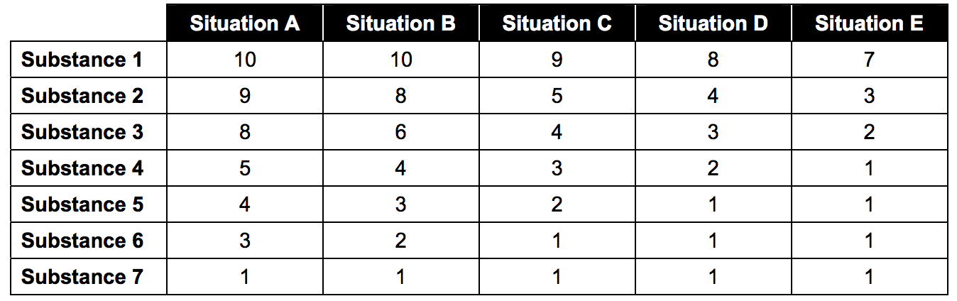
These two parameters combined give an indication of the type of effect that might arise if the isolation fails. (See Table 3 – Effects Matrix)
Table 1: Situation Parameter
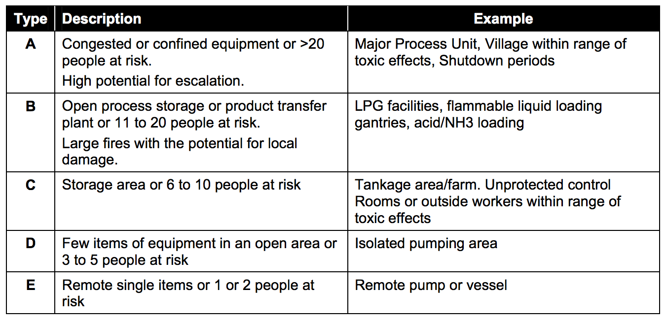
Note: The number of people at risk includes those not just in the immediate vicinity but those who could potentially be exposed to the hazard in the event of an uncontrolled release of energy.
Table 2: Substance Parameter
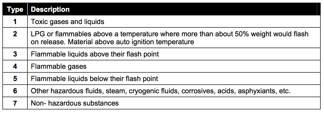
Table 3: Effects Matrix
Notes:
- Vapor cloud explosions in congested or confined areas or jet fires may have the potential for knock-on effects. Toxic releases may affect people over a wide area. If an escalation is likely, consider increasing the severity of the situation type to a higher category.
- In the case of a product containing more than one substance, use the most onerous substance type in the matrix.
Release Matrix
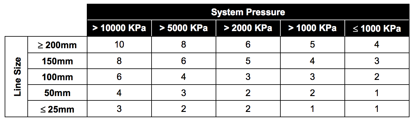
- Line size AND system pressure (these parameters will largely fix the potential release rate and, therefore, the extent of the area that could be affected)
These two parameters measure the effect’s size, and they provide a ‘release’ factor from the Release Matrix (see Table 4.)
Table 4: Release Matrix
Time Matrix
- Frequency of isolation procedure
- Duration for which isolation is to remain in place
Frequent isolation for relatively long periods needs to be of a relatively high rating than an infrequent one, which is to be in place for only a short time. These two parameters provide a ‘time’ factor from the time matrix (see Table 5.).
Table 5: Time Matrix
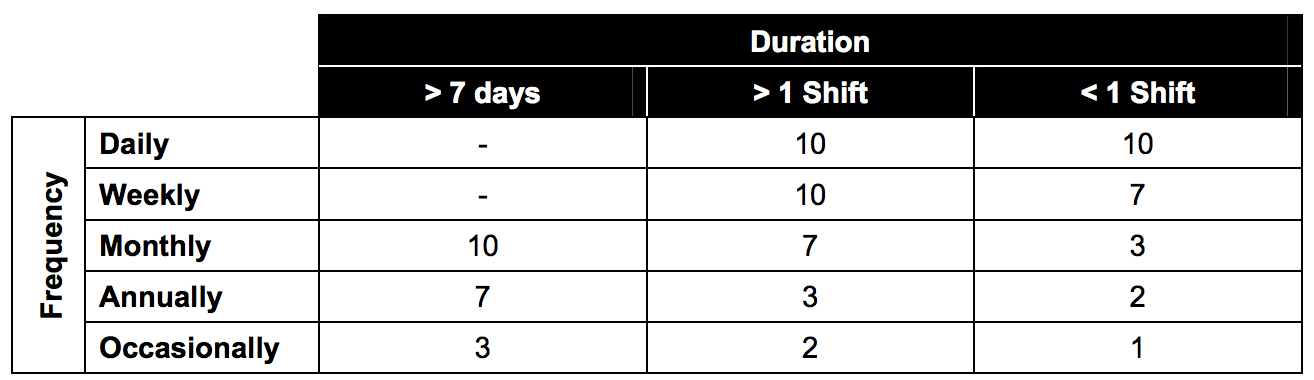
Note: More frequent isolation introduces a greater risk that increases as the intended duration increases. It is more difficult to maintain procedural controls due to handovers at shift change between different groups of workers.
In determining the frequency of isolation, account needs to be taken of the ‘group effect’ of several items of similar duty on a plant (e.g., a pump might typically require a seal change once every 12 months, and therefore the frequency of isolation in the ‘time matrix’ is annual). However, if four such pumps were installed, the isolation frequency would have to be increased to ‘monthly.’ (Note: that quarterly does not exist in the matrix.)
Similarly, the frequency of isolation must consider the ‘multiple effects’ where several isolations are needed to isolate an item of plant, e.g., isolating a section of line/equipment might require a single isolation from the energy source. If this happened every three years, the frequency would be ‘occasional’. However, if the line/equipment required three isolations to isolate (e.g., for a pump, from three separate suction lines from three feed tanks), the frequency would be increased
to ‘annually.’
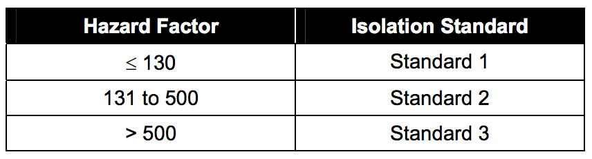
Hazard Factor
Combining the contributions of the three (3) factors derives the Hazard Factor for isolation:
Hazard Factor = Effects x Release x Time
The resulting Hazard Factor is a number in a range between 1 (trivial consequence) and 500+ (disastrous consequence)
Selection of Isolation Standard
There are three (3) Mechanical Isolation Standards:
Method 1: Single valve and bleed
Method 2: Double block and bleed
Method 3: Physical disconnection or spool removal and fitting of blank flanges, or insertion of spades or spectacle blinds.
The particular isolation method is selected by using the following Table 6.
Table 6: Isolation Standard Selection
Notes:
- In all cases, the seal integrity of each isolating valve for Standards 2 and 3 must be confirmed before issue of a Work Permit.
- Bleeds and vents should be closed once it is confirmed that the energies have been controlled.
CLICK HERE to Download this Guide from Minerals Industry Risk Management Gateway