
Since I shared my article last week on OSHA’s position of NOT allowing “exclusive control” to be carried over to process valves like we do with “cord and plug” electrical equipment, my international friends and clients have been having quite the chuckle at us here in the USA. They all say virtually the same thing… “you guys sure do make something so simple, very difficult”. Those of you that read my article and my position of what is declared “exclusive control” saw that I interject “risk assessments” into my Energy Isolation Control Plans, as this is how I was taught very early in my career. We did not have OSHA’s PRCS standard for several years when I started my career in the petrochem industry and thus we had to devise some other “standards” to ensure safe entry into our spaces. Having worked for several international companies, my corporate safety standards tended to have some really nice “international practices” sprinkled into them and I absolutely loved them as they were ALWAYS RISK-BASED – not the typical OSHA minimums approach. For example, The UK’s Health and Safety Executive (HSE) published their guidance on “safe isolation of plant and equipment” (HSG253). For those of you that have been interacting with me for 20 years know I have raved about this publication many times; it is the BEST guide for the “process industry” to understand how we MUST isolate our hazardous forms of energy and how different LOTO is for us then say an assembly style manufacturing plant. My good friends at The HSE were quick to remind me this weekend of this publication and in it, you will see where I got my rationale for my debate on “exclusive control” and why I am such a fanatic when it comes to the use of Double-Block-Bleed arrangements, rolling spool pieces, and blanking/blinding. This HSE document SEMI-QUANTIFIES the risks and provides us with the PROPER ISOLATION means to ensure our energy isolation method(s) are adequate for the hazardous form of energy and the work taking place (including the location of the work!). In this presentation an HSE HM Specialist Inspector (Mechanical) walks us through the Risk Assessment process to establish the minimum level of energy isolation – for those of you who love LOTO, this is about as sweet as it can get in our profession (IMHO)…
Design – New Plant
- Isolations should be included within design considerations
- It will be expected that for new plant HS(G) 253 is followed
- For other new plants, the selection tool in appendix 6 of HS(G) 253 should be used
- Any proposed deviation from the agreed design basis once the plant is operational should be justified by formal risk assessment before new isolation procedures are used
- The expected standard for new plant where there is to be entry, into areas containing toxics or where there is a high-pressure source is POSITIVE ISOLATION, with a suitable valve to allow the isolation to be made
Design – Existing Plant
- For an existing plant, the minimum standard is assessed using the tool in appendix 6
- For existing plant where HS(G) 253 cannot be met by current designs, an ALARP demonstration should be made and a time-bound action plan for improvements agreed
Plant identification
- All items required for safe isolation should be included within an isolation scheme
- Items of plant that are part of the isolation should be clearly marked as such
- Drawings should be produced to show how isolations should be made – these are not P&IDs but it may be suitable to modify P&IDs to clearly show isolation points
Pipework
- Pipework should be designed so as to limit the risk of trapped inventories and allow easy removal of fluids
- Isolation flanges or spool pieces should be easy to remove and replace but remain gas-tight in service
- See also Energy Institute guidance ‘Guidelines for the management of integrity of bolted pipe joints’
Valves
- Valves used for isolation must be designed for the isolation of the fluid involved
- Control valves are not generally suitable for isolations
- The best valves for isolation are ball valves and plug valves
- Some needle valves are good if designed for isolation duty
- Valve position must be clearly indicated
- Valves must be capable of being locked in the closed position
- Isolation valves will require maintenance
Blanks, Blinds and Spades
- More leak-tight than valves
- Provide positive isolation
- Need to be made to standards
- Need to be clearly marked
- Need to be compatible with the fluid(s)
- Need to be properly maintained and inspected before each use
- Need to be properly stored
Expected isolation standards for Control of Major Accident Hazards (COMAH) sites (i.e. PSM/RMP Sites in the USA)
How to work it out
Use the tool in appendix 6 of HS(G) 253
1. Substance Category of fluid 1 – 5 very toxic to not harmful
2. Release factor – size of line and pressure
3. Location factor – numbers at risk. You should include environmental considerations
4. Outcome factor – a combination of release factor and location factor (2 & 3)
OUTPUT: Use the Baseline Isolation Table using results at 1 (substance category) and 4 (Outcome Factor) above
Assessment Output
R – think again and see if you can do the job another way
I – POSITIVE ISOLATION
- COMPLETE separation of the plant/equipment to be worked on from other parts of the system; Physical disconnection (eg. spool removal/rolling)
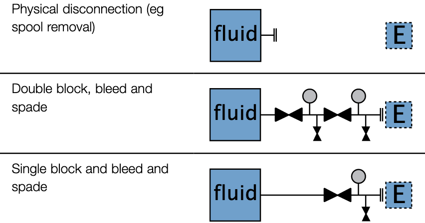
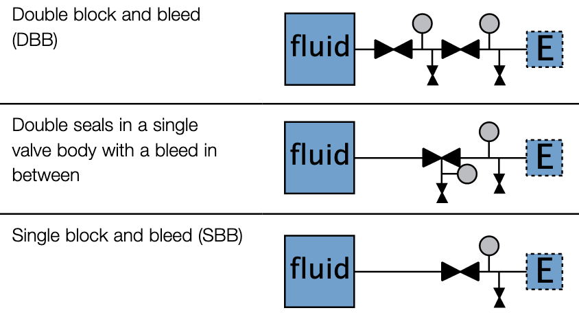
II – PROVED ISOLATION
- Valved isolation.
- Effectiveness of valve closure(s) can be CONFIRMED via vent/bleed points before intrusive work commences.
- Within this isolation category, the level of mechanical security is greatest for Double Block and Bleed (DB&B) and lowest for Single Block and Bleed (SBB).
- As a general rule, SBB should NOT be used with hazardous substances (see paragraph 120).
- Note for COMAH substances a MINIMUM of double block and bleed is expected.
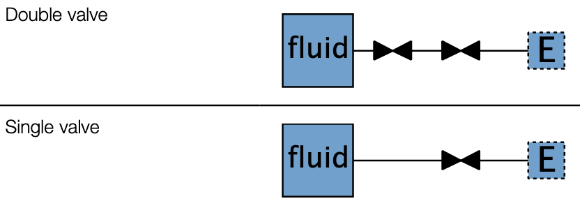
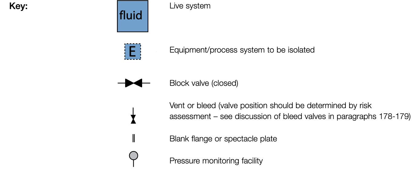
III – NON-PROVED ISOLATION
- Valved isolation.
- NO PROVISION TO CONFIRM THE EFFECTIVENESS of valve closure prior to breaking into the system.
- Where possible, double valve isolation should be used rather than single valve isolation.
NOTE – for confined space entry and extended-term isolations – DO MORE –Physical disconnection or insertion of spades
Substance Categories
| CAT 1 |
Very toxic (T+) Toxic (T) Carcinogenic Mutagenic toxic for reproduction Sensitizing |
| CAT 2 |
Extremely flammable (F+) Highly flammable (F) Flammable gases (R10) Flammable liquids (R10) – unless included in category 4 Petroleum products* – unless included in category 4 – consider whether category 1 is appropriate Oxidising (O) Explosive (E) Steam/Pressurised gases with a pressure of 10 psi or higher Flashing fluids Asphyxiants |
| CAT 3 |
Corrosive (C) Harmful (Xn) Irritant (Xi) |
| CAT 4 | Flammable liquids stored BELOW flashpoint, and BELOW flashpoint following release (R10) |
| CAT 5 | Non-classified and NOT stored in a potentially harmful state (e.g. under pressure or temp) |
Isolation Baseline Standard
|
Outcome Factor |
||||
|
A |
B |
C |
||
|
SUBSTANCE CATEGORY |
1 |
R |
I |
I |
|
2 |
R |
I |
II |
|
|
3 |
I |
II |
II |
|
|
4 |
II |
II |
II |
|
|
5 |
II |
III |
III |
|
Worked Example #1: 4” steam main at 175 psi, protection required for two fitters?
Substance Category
| Category | Description |
| 1 | Very Toxic, Toxic Carcinogenic, Sensitising, etc. |
| 2 | Flammables, Petroleum, Explosive, Steam, etc. |
| 3 | Corrosives, Harmful, Irritant |
| 4 | Flammable liquids stored below flashpoint and following the release |
| 5 | Non-classified & not stored in a potentially harmful state |
Release Factor
Table D – Release Factor for 4” steam main at 12 barg
| Pressure | ||||
| Line Size | > 100 psig |
< 100 psig > 10 psig |
< 100 psig | |
| > 8″ | H | H | M | |
| > 2″ < 8″ | H | M | L | |
| < 2″ | M | L | L | |
Location Factor
Table E – Location Factor
| H |
Any of: numbers at risk > 10; congested equipment; potential for escalation; large fires with potential for damage and multiple fatalities |
| M |
Typically: 3 – 10 at risk; uncongested plant, storage area or a small number of items in open area; minor fire |
| L |
Characterized by: 1 – 2 at risk; remote single items; easily contained minor fires |
Outcome Factor
|
Release Factor |
||||
| H | M | L | ||
|
Location Factor |
H | A | B | B |
| M | B | B | C | |
| L | B | C | C | |
So Isolation Baseline is II – PROOVED ISOLATION
|
Outcome Factor |
||||
|
A |
B |
C |
||
|
SUBSTANCE CATEGORY |
1 |
R |
I |
I |
|
2 |
R |
I |
II |
|
|
3 |
I |
II |
II |
|
|
4 |
II |
II |
II |
|
|
5 |
II |
III |
III |
|
CLICK HERE for more worked examples from the HSE