
When establishing our Hazardous Locations (HAZLOC) we utilize a Recognized And Generally Accepted Good Engineering Practice (RAGAGEP) such as NFPA 497, Recommended Practice for the Classification of Flammable Liquids, Gases, or Vapors and of Hazardous (Classified) Locations for Electrical Installations in Chemical Process Areas or there is also API RP500, Recommended Practice for Classification of Locations for Electrical Installations at Petroleum Facilities Classified as Class I, Division 1 and Division 2. Both of these RAGAGEPs manage flanges and fittings in a similar manner but I will use NFPA 497 in this article as it is more widely used.
PLEASE NOTE that API 500 is more forgiving in how it manages flanged and screwed connections, fittings, valves, meters, etc.
NFPA 497 allows for an area/room where there is flammable liquid piping passing through to remain UNCLASSIFIED as long as we have NO flanged and screwed connections, fittings, valves, meters, etc. that could leak into the area/room. This means that if the pipe was a SOLID run of pipe (welded connections count as a solid run of pipe) within the area/room, then we would NOT have to manage the area/room as an HAZLOC. However, if this run of pipe has any means in which the flammable liquid could leak from (e.g. flanged and screwed connections, fittings, valves, meters, etc.) then portions of this area/room MUST be managed as a Class I, Division 2 HAZLOC.
We know this from several references within our chosen RAGAGEP… (emphasis added by me)
5.4.1 Experience has shown that the release of ignitible mixtures from some operations and apparatus is so infrequent that area classification is not necessary. For example, it is not usually necessary to classify the following locations where combustible materials are processed, stored, or handled:
(1) Locations that have adequate ventilation, where combustible materials are contained within suitable, well-maintained, closed piping systems
(2) Locations that LACK adequate ventilation, but where piping systems are WITHOUT valves, fittings, flanges, and similar accessories that may be prone to leaks
(3) Locations where combustible materials are STORED in suitable containers
(4) Locations where the use of combustible liquids, or flammable liquids or gasses, will NOT produce gas or vapor sufficient to reach 25 percent of the lower flammable limit (LFL) of that combustible material
…
5.6.3 An operating unit could have many interconnected sources of combustible material, including pumps, compressors, vessels, tanks, and heat exchangers. These in turn present sources of leaks such as flanged and screwed connections, fittings, valves, meters, and so forth. Thus, considerable judgment will be required to establish the boundaries of Division 1 and Division 2 or Zone 0, Zone 1, and Zone 2 locations.
…
5.7.3 Continuous process plants and large batch chemical plants could be almost as large as refineries and should, therefore, follow the practices of the refining industry. Leakage from pump and agitator shaft packing glands, piping flanges, and valves generally increase with process equipment size, pressure, and flow rate, as does the travel distance and area of dispersion from the discharge source.
Two other keys to understanding this practice is how NFPA defines “Adequate Ventilation”, as the 5.4.1 application depends on the area/room having “adequate ventilation”:
3.3.1 Adequate Ventilation. A ventilation rate that affords six air changes per hour, 1 cfm per square foot of floor area (0.3 m3/min/m2), or another similar criterion that prevents the accumulation of significant quantities of vapor-air concentrations from exceeding 25 percent of the lower flammable limit (LFL).
The other assumption in my worked example is that the process equipment is SMALL/LOW or MODERATE, the pressure in the piping SMALL/LOW or MODERATE, and the flow rate in the piping is SMALL/LOW or MODERATE. These are quantified by NFPA 497 in the following way…
|
Relative Magnitudes of Process Equipment and Piping that handle Combustible Materials |
||||
| Process Equipment | Units | Small (Low) | Moderate | Large (High) |
| Size | gal | <5,000 | 5,000 – 25,000 | >25,000 |
| Pressure | psi | <100 | 100 – 500 | >500 |
| Flow Rate | gpm | <100 | 100 – 500 | >500 |
NFPA 497 offers us the following diagram to depict how such an area would be classified:
FIGURE 5.9.1(d) Leakage Located Indoors, above Floor Level. Adequate ventilation is provided. The material being handled is a flammable liquid.
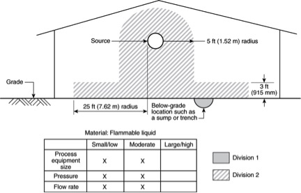
In 5.9.1(d) we see that the leak is
- INDOORS,
- ABOVE floor level, and
- ADEQUATE VENTILATION is present in the area/room
The diagram shows us that in this situation we have a 5’ bubble (10’ diameter) around the flanged and screwed connections, fittings, valves, meters, and so forth. Then extending down from our bubble, we find a space that is 10’ wide and extends ALL the way down to the floor/ground. And much like the other HAZLOCs for our flammable liquid(s) we use the 36” rule and 25’ buffer rule. This means that from the flanged and screwed connections, fittings, valves, meters, etc. the Division 2 HAZLOC will extend out 25’ at a height of 3’ (36″).
This means of establishing our HAZLOCs can be problematic in many ways in areas/rooms that contain flanged and screwed connections, fittings, valves, meters, and so forth. The most common violation is the use of forklifts that are NOT rated to be used in these areas/rooms. But it is also easy to find lighting that is hanging in these HAZLOCs as well as outlets and instrumentation that are located within these Div 2 HAZLOC.
PLEASE NOTE that the same practice is applied OUTSIDE of enclosed areas/rooms, but the distances are different.
FIGURE 5.9.1(b) Leakage Located Outdoors, above Grade. The material being handled is a flammable liquid.
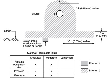
We can see our bubble is only 3′ radius (6′ diameter), with a 10′ radius that is 18″ high. It is understood that “outdoors” we always have better ventilation ABOVE GRADE and thus the more forgiving distances.