
If I had a dime for everytime someone says to me… “where do you come up with all this sh_t?” during our deep discussions on process safety topics. And whenever I do my 5-day Process Safety course we seem to always get deep into the “process safety weeds” and one topic that many students are amazed by is that there is a RAGAGEP for just about all of our needs. The one task that we struggle to find guidance on is Line Breaking, but don’t worry too long, as we do have a RAGAGEP on what type of energy isolation would be acceptable for all sorts of work tasks. Those of us who have experience with isolating Permit-Required Confined Spaces (PRCS) will be familiar with Double Block & Bleed (DB&B) and Blinding/Blanking. I learned of this RAGAGEP while working on a Bromine design project at one of my former employers and was amazed at the level of the engineering review associated with “equipment isolation for maintenance and entry” the engineers were taking on – before the project was even funded! They were using a Norwegian Standard from The Norwegian Oil Industry Association (OLF) and The Federation of Norwegian Industry. The standard is NORSOK STANDARD P-001, Process Design, which contains an entire section on the “acceptable energy isolation” based on the risk. A really neat standard and it brings a lot of rationales when trying to decide if “single valve isolation” is acceptable or if the task needs “Double Block and Bleed isolation”. Check out the standard and give it some serious consideration if you’re looking for some concrete engineering logic behind your energy isolation needs.
System and Equipment isolation
It shall be possible to isolate equipment, instrumentation, valves and process sections during maintenance work to obtain safe working conditions for the maintenance personnel. The MINIMUM ISOLATION LEVEL required shall be thoroughly considered for all systems where intervention during operation can be required. This consideration shall be based on the risk associated with the intervention operation, including
• requirement for equipment entry during operation,
• fluid category (level of hazard involved, e.g. flammability, toxicity),
• operating pressure and temperature,
• pipe dimension and system volume,
• duration of operation,
• frequency of operation
Specific criteria for the selection of isolation level shall be provided by the project owner. The type of valves selected for isolation purposes shall be based on a thorough evaluation of requirements and inherent valve characteristics.
Physical separation
This is the highest standard of isolation and is accomplished through one of the following arrangements to prevent seepage of any fluid:
• spectacle blind;
• spade and spacer;
• spool piece to be removed and blinding off the open pipe end.
It normally requires an initial isolation (see 7.1.3) to be in place in order to install a physical separation. When sandwich type butterfly valves are used, an additional flange shall be provided between the valve and the spool piece to allow for spool removal without disturbing the butterfly valve.
All vessels that can be entered shall be equipped with physical separation on all nozzles (including PSV nozzles), except for nozzles not permanently connected to any system. Physical separation shall be located as close to the vessel as practical, normally directly on the nozzle. For level instruments, physical separation may be combined and shall then be located on the common closed drain connection.
Spool pieces shall be used when necessary for maintenance purposes. After removal of spool piece, a blind can be installed to achieve physical separation. This requirement applies to pumps, compressors and heat exchangers.
Level of Isolation
General
The order of the isolation levels listed below reflects the standard of isolation with the highest standard of isolation listed first.
To achieve double block and bleed isolation, a single valve is acceptable ONLY if the force acting on the seal faces is independent of system pressure, AND if a bleed connection is provided between the two (2) seal faces (typically a double expanding gate valve). Further, such a valve shall have means to keep the valve in closed position to avoid malfunction or mal-operation.
PHYSICAL SEPARATION with DOUBLE BLOCK AND BLEED
This is the HIGHEST STANDARD OF ISOLATION and provides a valved barrier by closing two (2) block valves in series and using a bleed point in between to prove isolation point integrity. The double block and bleed arrangement provides the initial isolation to install the physical separation, see Figure A.1.
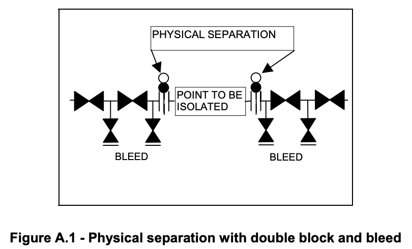
During installation or removal of the physical separation, it shall be possible to bleed down the trapped pressure by a valve. (NOTE the valve in Figure A.1 above that is between the “point to be isolated” and the closest valve in the DB&B arrangement)
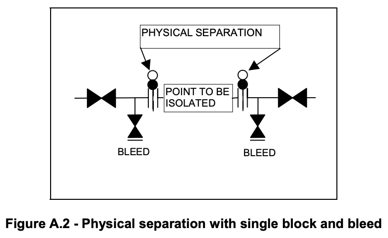
PHYSICAL SEPARATION with SINGLE BLOCK AND BLEED
A single block isolation provides a valved barrier by closing a single block valve. The single block arrangement provides the initial isolation to install the physical separation. There shall be possibilities for testing the isolation point integrity by bleeding off the pressure and monitoring the pressure at the point to be isolated, see Figure A.2.
DOUBLE BLOCK AND BLEED
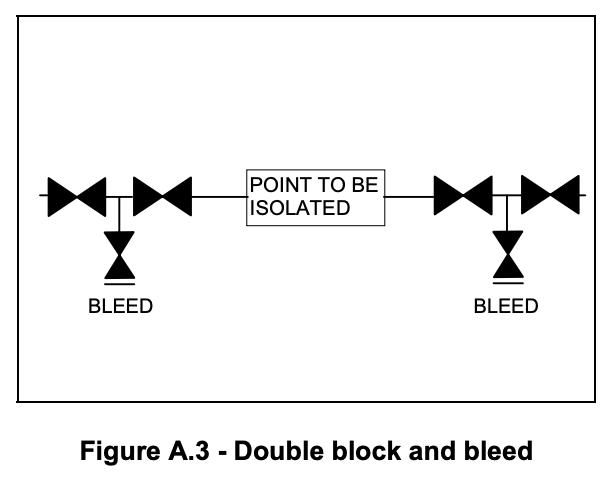
A double block and bleed isolation provides a valved barrier by closing two block valves in series and using a bleed point in between to prove isolation point integrity as shown in Figure A.3.
DOUBLE BLOCK
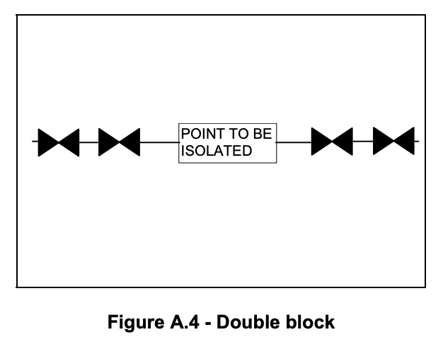
Double block isolation provides a valved barrier by closing two block valves in series. There shall be possibilities for testing the integrity of the barrier by bleeding off the pressure and monitoring the pressure at the point to be isolated, see Figure A.4.
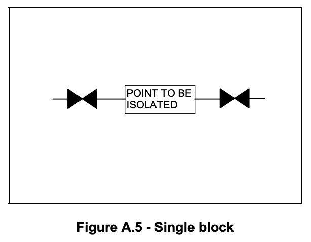
SINGLE BLOCK
A single block isolation provides a valved barrier by closing a single block valve. There shall be possibilities for testing the integrity of the barrier by bleeding off the pressure and monitoring the pressure at the point to be isolated, see Figure A.5.
Redundant train/process section For equipment and valves located within a redundant train/process section that can be isolated, the means for isolation/physical separation for the train/process section can be used.
Isolation Standards
There are three Isolation Standards:
- Standard 1: Single valve and bleed
- Standard 2: Double valve and bleed
- Standard 3: Physical disconnection or spool removal and fitting of blank flanges, or insertion of spades or spectacle blinds
ISOLATION STANDARD 1
This represents the lowest level of isolation and care shall be taken to ensure proof of an effective seal.
- Single block valve isolation uses an adjacent drain valve to assist in detecting an ineffective seal.
It is applicable for:
- Hot, flashing NON-flammable liquid (e.g. domestic hot water) at all pressures
- Non-flammable, NON-flashing, non-toxic, non-irritant liquids (e.g. firewater, potable water, cooling water) at all pressures
- Non-flammable, NON-toxic gases (e.g. plant air, instrument air, nitrogen gas) at <145 psi.
ISOLATION STANDARD 2
The double block and bleed valve arrangement consist of two (2) separate block valves in a line, with a bleed valve in the connecting line between them. Ideally, the two (2) block valves are located relatively close together. The bleed is to be routed to a SAFE LOCATION but should be VISIBLE and ACCESSIBLE to confirm an effective isolation. The bleed valve normally has two (2) functions:
- to indicate if the upstream valve is passing, and
- in the event of the upstream valve passing, the bleed prevents pressuring the line between the block valves (in this circumstance the drain line must be directed to a safe location and monitored).
The following issues should be considered when using bleed valves:
- The possibility of bleed valve blockage
- Ensuring the process operator can detect flow through the bleed when checking the integrity of isolating valves
- Ensuring that bleed valves are accessible
- Blind off bleeds where possible when they are closed during normal plant operations
- Diversion of any excess leakage to a safe location
STOP WORK if the bleed is passing significant quantities as pressure may increase between the double block valves possibly causing the downstream block valve to leak. This method of isolation shall be deemed invalid if the bleed section of the isolation cannot be fully depressurized to the atmosphere.
It is applicable for:
- Flammable, flashing liquids and flammable gases (NOT hydrogen) at all pressures
- Toxic gases or toxic liquids at all pressures
- Flammable liquids at all pressures
- Non-flammable, hot, flashing liquids at all pressures
- Non-flammable, non-toxic, non-irritant liquids at high pressures (e.g. process cooling water at >245 psi and liquid nitrogen at all pressures)
- Non-flammable, non-flashing, non-toxic, non-irritant, asphyxiant gases (e.g. nitrogen gas, CO2)
- Non-flammable, non-flashing, toxic and/or irritant liquids (e.g. treatment chemicals, hypochlorite, biocides, scale and corrosion inhibitors, demulsifiers) at all pressures.
ISOLATION STANDARD 3
This standard provides a positive and HIGHEST LEVEL OF ISOLATION. It provides a high integrity physical barrier between the hazard (energy) and the environment in which work is being done.
Physical disconnection should be achieved whenever it is reasonably practical to do so. It is easier to visually monitor a removed spool than to visually check if a spectacle blind has been installed. Similarly, a spectacle blind should be used in preference to a spade.
It is normally applicable for:
- Confined Space Entry
- The opening of equipment for maintenance while the remainder of the unit is in operational service and there is a consequent high level of risk of uncontrolled energy release
- The opening of equipment when the remainder of the unit, though not in operation, contains hazardous materials and there is a high level of risk of uncontrolled energy release
- Hydrostatic testing of equipment
- Hot work on pressurized hydrocarbon systems
- Long-term isolations.
Implementing Isolation Standard 1
When isolating non-hazardous systems establish the single valve isolation and conduct valve integrity test by checking for leakage. When isolating a hazardous system (having considered this action as part of a rigorous risk assessment) the following requirements must be met:
- The fire and gas detection system in the area shall not be inhibited
- No hot work permits allowed within a minimum of a 50′ radius of work
- On-going integrity of the sealing valve must be monitored
- The work site shall be monitored by a Process Technician.
Implementing Isolation Standard 2
Isolation Standard 2 requires bleed valves to be available to enable block valve integrity to be determined. The system inventory (i.e. the live plant), is the normal medium used for testing valve integrity. Additionally nitrogen or water from an external source can be used. In pressure systems that have liquid inventories only, use an open bleed valve to monitor for any visual leakage in the section of piping between the closed block valves to show block valve integrity. Valves operating as shut-off valves should not allow any visual seepage of liquids across their seats over a 30 minute monitoring period.
In pressure systems containing gas, use a pressure gauge fitted to the bleed valve to monitor pressure build-up or fall off to show block valve integrity. The block valves should not allow gas to leak at a rate where a hazardous pressure build-up can develop in the downstream piping.
Implementing Isolation Standard 3
Before breaking containment to insert a blind or remove a spool piece, ensure that:
- Adequate valve isolation is in place
- Successful integrity tests have been carried out on all block valves in the isolation scheme
- The piping has been proven to be depressurized and free from hazardous fluids on both sides of the flange to be broken
- The order in which blinds are installed is high-pressure lines, low-pressure lines and finally
- Pressure Safety Valves and blowdown valves (upstream valve first).
When carrying out the isolation consider the following:
- The Permit Issuer shall consider the implications of the work on the safety of personnel and equipment involved and the impact of any other work planned in the area
- Ensure adequate Personal Protective Equipment is available and in use
- Ensure all Blinds and gaskets are rated for the line class
- Ensure all Blinds and gaskets are manufactured of a material suitable for the application (e.g. acid lines etc.)
- Fit new gaskets as required
- Loosen all bolts on the far side of the flange to ensure that any stored contents/pressure will be released in a direction with least risk
- Fit all flange bolts and tighten to the specified torque in the correct sequence.