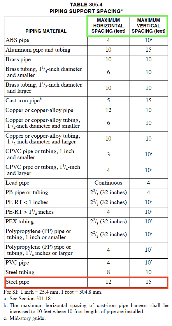
As we have discussed here many times, our piping is our “primary containment” that seems to be where the vast majority of Loss of Primary Containment (LOPC) events occur. Many reasons for this, which we have spelled out in other postings, but none the less the vast majority of “leaks” occur in our piping. One means that we should be abiding by is “proper support” of our piping and believe it or not we have some concrete guidance as to how far our supports can be spaced. Most states in the USA have adopted some version/edition of the International Mechanical Code (IMC). This “state code” has some maximum spans for pipe runs and these requirements become a baseline for a PSM/RMP covered process. I should also point out, these requirements kick in for those of you who have far less than OSHA’s or EPA’s PSM/RMP Thresholds for PSM/RMP; so these requirements will affect almost all processes with a “hazardous material”.
Chapter 3 of the IMC, Section 305 – Piping Support essentially limits the “steel pipe” for horizontal pipe runs to 12′ without having support. Vertical runs can span 15′ without proper support. See Table 305.4.

PLEASE NOTE: the IMC 2015 does allow for the designer to use ANSI/MSS SP-58, Pipe Hangers And Supports – Materials, Design, Manufacture, Selection, Application, And Installation rather than meeting the minimums found in Table 305.4.
Where does this limitation come from?
This 12′ (10′ in some states) comes from sound pipe design and installation requirements. ASME B31.3 is the baseline for almost all HAZMAT piping in the USA and this standard requires the piping to be pressure tested AFTER it is field-erected AND BEFORE it is placed into service. The code specifies this pressure test must be a hydrostatic pressure test unless the user/owner can justify that the introduction of a liquid can cause safety or quality issues; then the pressure test can be a pneumatic pressure test using a “dry gas”. So with the baseline requirement that all piping installed under B31.3 be pressure tested and that test must be a hydro test, the piping must be designed to “support” the weight of the pipe when it is completely filled with water.
For example, a 10′ run of newly installed 3″ carbon steel pipe will weigh 130 pounds just by itself. Add a valve or two and insulation (for when the pipe may be pressure tested at a later date – NOT new) and we can easily exceed 300 pounds. Some of you may have even larger “headers” where the pipe diameters can be upwards of 24″ in diameter and now we are talking about some serious weight! Now we’re talking about 5,000 pounds of weight with just a straight run of pipe (no valves or insulation).
From an engineering perspective, we MUST consider these factors when considering our pipe supports:
Pipe Support Span – the optimum distance between two supports so as to avoid excessive sagging. Pipe span varies with changes in:
- Pipe Material of Construction
- Nominal Diameter of pipe & its schedule (e.g. wall thickness)
- Type of service (liquid vs gas/vapor)
- Type and Thickness Insulation
Thus when establishing the piping support, we MUST consider the following:
- Own Weight Of Pipe
- Insulation Weight
- Weight of Fluid During operation
- Weight of hydrostatic fluid During Hydro Test
- Weight of Valve(s), Flanges, Strainer(s), specialty inline items, etc.
PLEASE NOTE: the engineering does NOT and should NEVER attempt to allow a pipe to be supported from another pipe!!!
So as we can see, the baseline of 12′ (some may use 10′) is justified even for those rare occasions when the pipe needs to be hydro’ed. The chemical industry has had its share of events where the pipe runs collapsed (even some elevated vessels) during their hydro tests and this led to significant issues.
So once again we can learn a lot from our baseline codes (e.g. RAGAGEPs). This is NOT world-class safety, just baseline requirements that many miss in their design and fabrication of chemical processes.
CLICK HERE for free access to the IMC