
The purpose of this Safety Alert is to highlight the risks associated with compromised pressure relief circuits on Cryogenic Tank Containers. Cryogenic Tank Containers are commonly used for transportation and/or storage of cryogenic liquids, including, but not limited to, Nitrogen, Oxygen, and Argon.
A large explosion occurred at a cryogenic gas transport depot in Tamworth, NSW, in a cryogenic tank container containing 25,000 liters of liquid nitrogen, destroying the container and trailer and damaging nearby structures. The worker on-site at the time suffered minor injuries from a fall. Debris was scattered over an area of approximately 5,000 square meters.
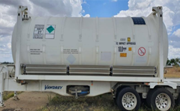
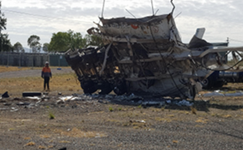
In this incident, the cryogenic tank container filled with liquid nitrogen catastrophically ruptured after the pressure increased beyond the maximum allowable working pressure of 1,000 kPa, and the pressure safety valves failed to operate.
The cryogenic tank container had two pressure safety valves fitted on a common pipe, both set at 1,000 kPa. The pressure safety valves had been periodically inspected and tested.
The investigation concluded that the root cause was a blockage in the pipe feeding the two pressure safety valves, most likely due to ice.
The design of the internal pipework leading to the pressure safety valves on this tank was more susceptible to a blockage than that of other cryogenic tanks. This was due to a low point, in which moisture could accumulate, and the fact that the pipe leading to the pressure safety valves was independent of all other lines, limiting the ability to purge it dry.

Action required
Work Health and Safety legislation requires the person with management or control of plant at a workplace must ensure, so far as is reasonably practicable, that the plants are without risks to the health and safety of any person.
Specific control measures
The following risk control measures are recommended for all Cryogenic Tank Containers.
Acceptance testing to be carried out for Cryogenic Tank Containers
Acceptance testing needs to be performed when a newly purchased or leased Cryogenic tank is put into service in Australia. It is not adequate to simply rely upon manufacturers’ test certificates. Pressure relief circuits need to be tested, for example, by increasing pressure in a vessel under controlled conditions, until the pressure safety valves lift, to demonstrate that:
- The pressure safety valves work.
- Pressure safety valve pipework is clear and full flow is possible.
Purge procedures (checking / purging every outlet pipe, especially pipework leading to pressure safety valves)
Purge procedures for Cryogenic Tank Containers must ensure that pipework leading to pressure safety valves is specifically purged and checked for moisture. This may require specific procedures to be developed to ensure every section of pipework is adequately purged and checked for moisture, especially pipework leading to pressure safety valves.
Maintenance requirements for Cryogenic Tank Containers
Maintenance teams must be trained and made aware of the following: Potential issues associated with moisture accumulation and the need to prevent or minimize moisture ingress when containers are opened to the atmosphere.
- The need to continuously purge all outlet points, especially those associated with pressure safety valves, once a container is opened to the atmosphere.
- Need to test the pipework leading to the pressure safety valves for moisture following maintenance.
- Examples of specific purge procedures are:
- Purge times, temperatures, and quantities.
- Maintaining the plant under a slight dry nitrogen positive pressure when opened to the atmosphere.
- Where practical, use a borescope to confirm no water accumulation in relief pipework.
Pressure safety valves best practices:
Procedures relating to pressure safety valves must ensure the following:
- Every pressure safety valve should be checked closely against its Safety Valve Test Certificate prior to installation on a tank (especially serial number, set pressure, next test due date).
- A pressure safety valve should not be installed on a tank if any irregularity around performance is noted on its corresponding Safety Valve Test Certificate (lift and/or reseat pressure for example).
- A check must be made prior to installing any pressure safety valve to ensure that the locking wire is intact, sealed, and secured.
- Any pressure safety valve found in service without a properly sealed locking wire should be treated as potentially inoperable.
- When removing for maintenance, seal off the pressure safety valve connection opening as soon as practical to minimise moisture ingress or maintain plant under slight positive dry nitrogen pressure.
Remote monitoring of Cryogenic Tank Container pressure via telemetry (recommendation):
Since remote monitoring of Cryogenic Tank Container levels and pressures via telemetry has become much more robust and affordable than it used to be, it is recommended that remote telemetry systems should be installed on Cryogenic Tank Containers that are not subject to regular visual checks.
Any such telemetry solution should incorporate alarm points with automatic notifications to internal emergency response teams when normal operating parameters are breached. In virtually all circumstances, this would allow sufficient time for manual intervention before a critical threshold is reached.
Source: NSW SafeWorks