
With this week’s event in Japan, where the roofs of the flammable liquid storage tanks were blown off, I shared OSHA’s “emergency venting” requirements to explain why the roofs were off the tanks, which sparked a lot of sidebar discussions. Sizing these emergency venting options is quite easy, as I explain in this article with the help of Super Grok. Although I was disappointed in the errors it made and the image it produced. BE CAREFUL with AI! That emergency vent is a tad too large for that “gasoline” storage tank, but hey, it stands out for an educational image!
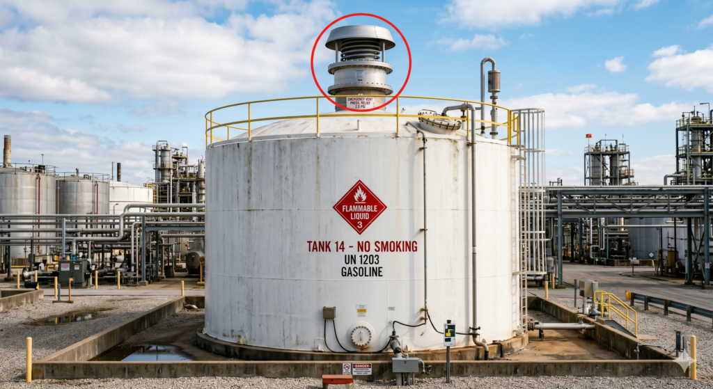
Sizing emergency venting for atmospheric storage tanks is primarily governed by API Standard 2000, Venting Atmospheric and Low-Pressure Storage Tanks and NFPA 30, Flammable and Combustible Liquids Code. We can also use OSHA’s 1910.106 standard, although it is very dated, so most will use API or NFPA.
The primary driver for emergency venting is fire exposure, which causes rapid vaporization of the stored liquid.
Determine the “Wetted Area” (Aw)
The wetted area is the surface area of the tank shell in contact with the liquid that can be heated by an external fire. The calculation varies by tank geometry:
Vertical Tanks: The wetted area is the surface area of the shell up to a height of 30 feet (9.14m) above grade. The tank bottom and roof are generally excluded.
Horizontal Tanks: Calculated as 75% of the total exposed surface area.
Sphere/Spheroid: Calculated as the area up to the maximum horizontal diameter or a height of 30 feet, whichever is greater.
Calculate the Required Venting Capacity
The venting capacity is expressed in Standard Cubic Feet per Hour (SCFH) of air. There are two (2) ways to determine this:
Option 1: The Tabular Method (For Hexane-like Liquids)
If the stored liquid has characteristics similar to hexane, you can use the simplified tables in API 2000 or NFPA 30.
For Aw < 2,800 square-feet: Use the specific SCFH values provided in the tables based on your calculated wetted area.
For Aw > 2,800 square-feet: The required capacity is often calculated using the formula:
CFH = 1,107 X Aw ^0.82
Option 2: The Heat Input Method (For Other Liquids)
If the liquid is significantly different from hexane (e.g., high latent heat), use the heat absorption formula:
Q = 21,000 X Aw^0.82 X F
Where:
Q = Total heat absorption (BTU/hr).
F = Environmental factor (e.g., 1.0 for bare metal, 0.3 for certain insulation, 0.5 for water spray).
Once you have Q, calculate the vapor flow rate (W) based on the latent heat of vaporization (L) of the liquid:
W = \frac{Q}{L}
Finally, convert this mass flow to an equivalent air flow (SCFH) to select the vent.
Account for Reduction Factors
You can reduce the required emergency venting capacity if the tank has specific safety features:
Drainage: If the tank area is graded to drain spills away, the heat input can sometimes be reduced.
Insulation: Credit is given for fire-resistant insulation that remains in place during a fire.
Water Spray/Deluge: NFPA 30 allows a reduction factor (usually F=0.3) if an approved water spray system is installed.
Select the Venting Device
The total required capacity is the sum of Normal Venting (breathing) and Emergency Venting. You can achieve this via:
Emergency Relief Vents: Weight-loaded or spring-loaded hatches that lift at a set pressure.
Frangible Roof-to-Shell Joint: For certain large vertical tanks (API 650), the roof-to-shell weld is designed to fail preferentially, acting as a massive emergency vent.
Gauge Hatches/Manway Covers: Specialized “long-bolt” manways that allow the cover to lift under pressure.
Key Constraints to Remember
Set Pressure: The emergency vent must be set to open at a pressure higher than the normal PV (Pressure-Vacuum) valve but below the tank’s Maximum Allowable Working Pressure (MAWP).
Vacuum Relief: Emergency venting usually only addresses overpressure. Ensure your normal venting is sufficient for vacuum (inbreathing) during liquid pump-out or rapid cooling.
MAWP vs. Design Pressure: For atmospheric tanks (API 650), the design pressure is often very low (e.g., 0.5 to 2.5 psig). Ensure the vent is sized so that the “full-open” pressure does not exceed the tank’s structural limits.