
This picture represents the fun side of working with clients who want to be world-class and meet the “intent” of a code or standard, not worrying if it just meets OSHA. This is a refrigeration client who is really trying to make this start-up an example for other facilities within the organization to emulate. During a Pre-PSSR (before the official PSSR) we came across an inherited set up which is not the best.
Could OSHA/EPA/AHJ take issue with it, probably not before the event, but it would be painfully obvious after the “event”.
What event am I speaking of and what RAGAGEP could/would OSHA/EPA/State Fire Marshal point to as a violation?
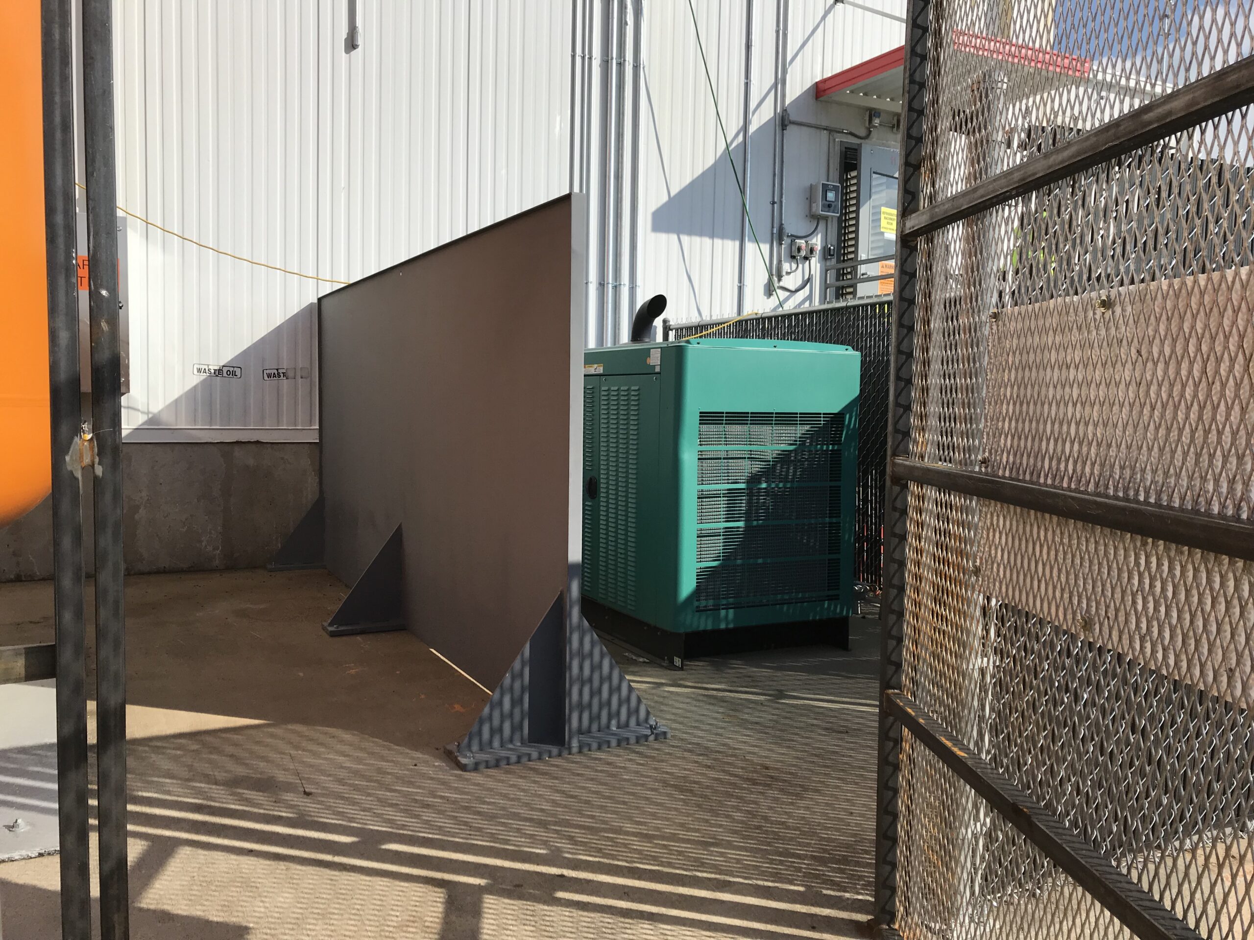
During our walk-down of the process, we came across this arrangement (shown below).
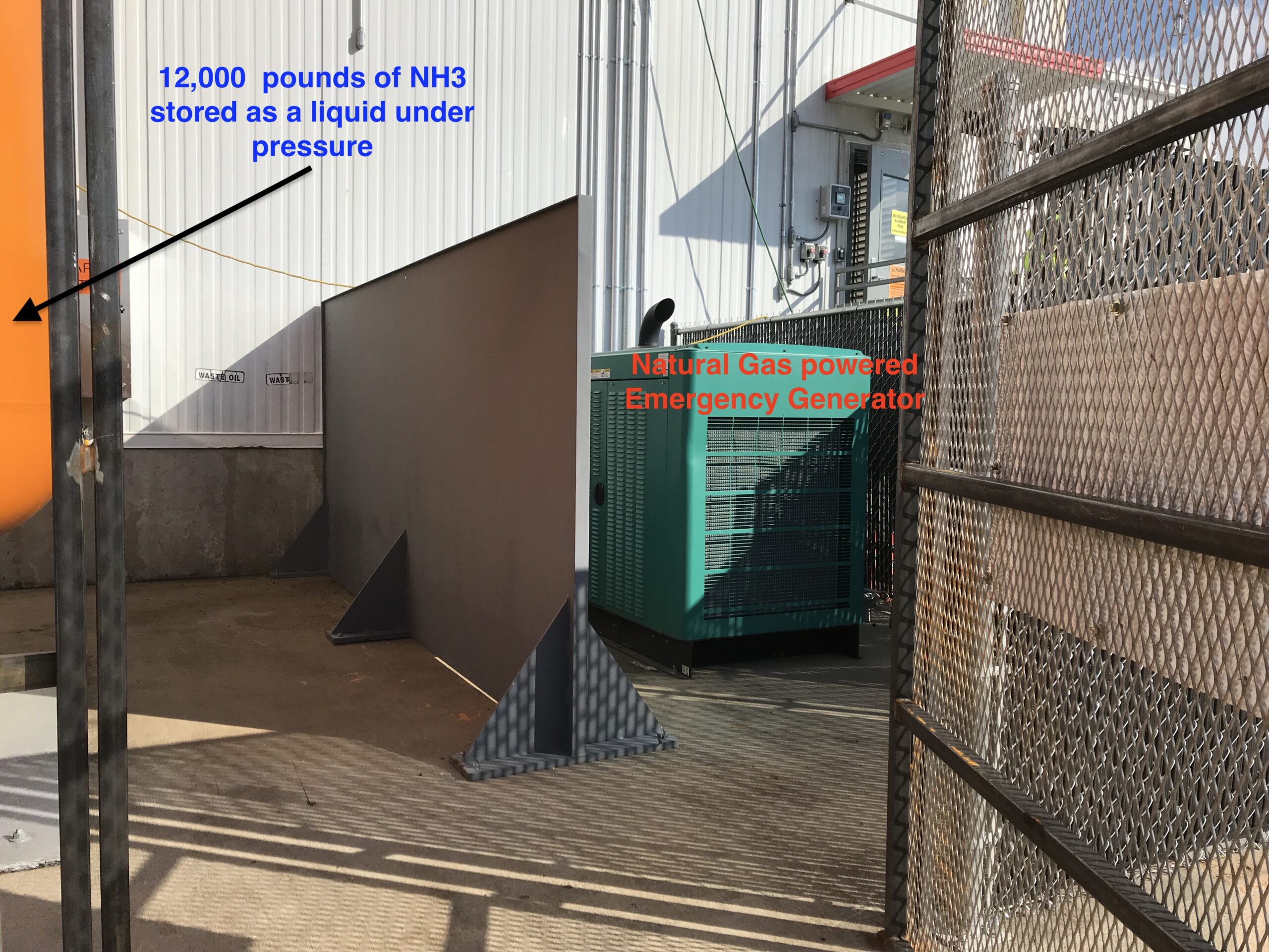
That is an emergency generator, powered by a Natural Gas Feed just on the other side of the generator/fence (to the right in the pic), that comes off the 4″ main line to the plant. So what happens if we have a “generator fire” or a “Gas leak jet fire” feed by an unended supply of Natural Gas? This is what we saw in our heads…(minus the barrier of course)
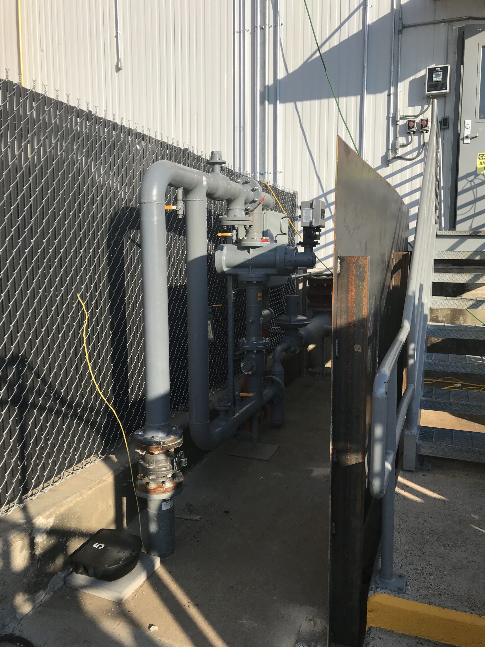
Shown below is the NG feed on the other side of the generator/fence, this 4″ NG feed is ~15′ away and it too poses a SERIOUS FIRE risk to the HPR.
Take note that the 1/2″ steel plate next to the stairs is to provide a fire rated barrier to the egress stairs shown to the right. Bottom line, why we do not consider the location of our main gas lines coming into our facilities still puzzles me. I have dozens of photos of these types of issues with covered process exposures, smoking areas right next to main feeds, in the middle of parking lots with not vehicle barriers, etc. True, NG is exempt from PSM in most cases as it is used solely as a “fuel”, but this Cat 1 Flammable Gas deserves some respect and where we put it and what we build around it MUST receive some SERIOUS consideration.
This is why a process walk-down during a PHA and the PSSR is absolutely critical, especially when performing the Facility Siting assessment of the PHA.
Now there are plenty of folks who would say… “Bryan, show me the standard or code that prohibits an N.G. powered generator from being 7′ from my High-Pressure Receiver with 12,000 pounds of Liquidfied Pressurized NH3”.
This client understood where I was going before I even took my eyes off the generator and turned my head to say… “XXXXXXX”
They were already on the same page and said: “Damn it, how did we miss this?”
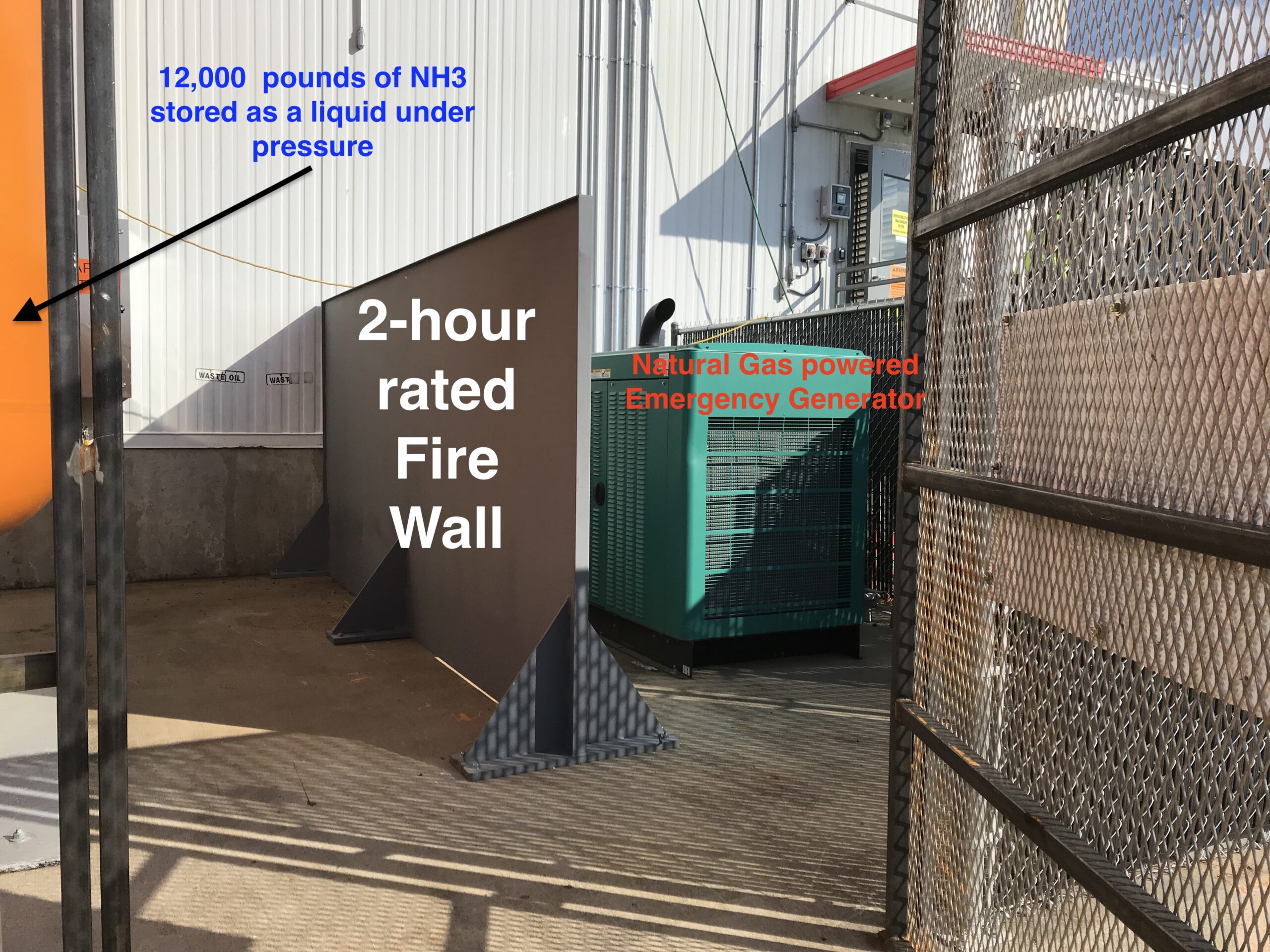
So this is what they have now…, as well as the code that would be used to cite them should the generator be a fire source for our HPR.
The design RAGAGEP used in the refrigeration industry is ANSI/IIAR 2-2014. And in this code/standard, the storage of combustibles within a machinery room is PROHIBITED…
6.4 Combustible Materials. Combustible materials shall not be stored in machinery rooms outside of approved fire-rated storage containers.
EXCEPTION: This provision shall not apply to spare parts, tools, and incidental materials necessary for the operation and maintenance of the refrigeration system.
But Bryan… this is clearly not inside a machinery room, it is outside. That is an astute observation Watson, it is indeed outside. And I will go one step further, the “fire scenario” that we do our sizing basis on (shown below) is a “pool fire” involving flammable/combustible liquids or a large fire load of ordinary combustibles. No mention of a “jet fire” RV sizing basis – do we know why there is no such RV sizing basis for a “jet fire” impacting your PV? BECAUSE WE’RE NOT SUPPOSE to have high-pressure flammable gas lines, NOT ASSOCIATED with our process, locate such that they could CAUSE A SERIOUS PROBLEM for our PV’s!
We then looked to 15.3.7 *Pressure Relief Device Capacity Determination which covers our Relief Valve Design/Sizing Basis for a “Fire Scenario”, which is used 99.9% of the time in these types of operations. This section states:
15.3.7.1 Pressure relief devices shall have sufficient mass flow carrying capacity to limit the pressure rise in protected equipment to prevent catastrophic failure. The minimum required relief capacity shall depend on the equipment being protected, the effects of inlet pressure losses, and the scenarios under which overpressure is being created. This relief capacity protection includes heat loads from cleaning operations and process loads.
15.3.7.2 The following sources of heat loads that can lead to overpressure shall be considered when determining the pressure relief device capacity for ammonia-containing equipment. It is permissible to use manufacturer’s data when determining relief requirements. All applicable heat loads capable of causing overpressure shall be considered, and the capacity of the pressure relief device shall be based on the scenario with the largest capacity requirements:
15.3.7.2.1 Overpressure Due to External Fire
So the basic sizing basis is assuming there are NO COMBUSTIBLES within 20′ of the pressure vessel. But if we do have a fire load within 20′, our sizing basis changes…
15.3.8 *Where combustible material is stored within 20 ft (6.1 m) of a pressure vessel that is outside of a machinery room, the relief device capacity factor, f, in the formulas shall be increased to f = 1.25 (f= 0.1).
A.15.3.8 It should be noted that IIAR 2 requires application of the increased relief capacity factor for materials that are “stored” within 20 ft of a pressure vessel, whereas ASHRAE 15 requires application of the increased relief capacity factor for materials that are “used” within 20 ft of a pressure vessel. The technical concern relates to increased exposure of the pressure vessel to an external fire, and IIAR 2 takes the position that “storage” of combustible materials adjacent to a pressure vessel constitutes the more accurate description of a scenario warranting application of the additional safety factor.
The fire scenario in this example is actually worse as it is not necessarily a “pool fire” but more of a “jet fire” from a flammable gas that has a large capacity to generate heat when burned (i.e. why we use NG for our comfort heating!). With the main feed being less than 20′ away we had four (4) options:
- Move the Gas Feed away from the Process, or
- Move the Process away from the Gas Feed, or
- Size the RV’s according to 15.3.8, not 15.3.7.2.1 or
- Construct at least a 2-hour fire rated barrier between the NG source and the “process” (Note: we selected a 2-hour rating for just extra protection/time, as a tad thicker plate was not that much more $ and it bought us some more time to get the gas shut off at our remote location and the gas between the isolation valve and the generator/leak point at the feed by the process to burn off.)
The facility “chose wisely” as the fire barrier is the best feasible choice. Having a potential “jet fire” scenario in the area of your primary NH3 storage vessel is not a pretty scenario and I might add, a BLEVE scenario as well!
Inside or outside, fire is a MAJOR threat to our pressure vessels. For someone to make the argument that all of this is “overkill” and that IIAR-2 does not cover vessels outside, just does not understand the underlying principles of process safety or risk management. Overkill would be me, telling them they need to move the Main NG feed or the Engine Room. Had this been a “new construction” project I would have most certainly suggested, might strongly I would add, the engine room and the 4″ gas main be separated by some distance greater than 15′. But this is an inherited problem and safety engineers are paid to ENGINEER OUT RISKS, so we discussed our \options and they chose wisely with the fire barrier.