
Simply put, “corrosion allowance” is an extra amount of thickness added to the thickness of the pipe/vessel wall based on the expected exposure the pipe/vessel may see during its lifespan. Typically, my experience has been that corrosion allowance has a safety factor equivalent to 2 when the vessel/pipe was knowingly going to be exposed to external and/or internal corrosive conditions. This is intended to extend the life of the vessel/pipe, as it is extremely rare for carbon steel not to see corrosive conditions – just normal atmospheric condition can cause external corrosion on a poorly maintained vessel/piping. So why should I care about it?
The big reason why we care (or should care) is that the corrosion allowance plays a big role in our vessel inspections, especially “well seasoned” (e.g. old) vessels!
Recently I have learned of new vessels constructed with zero corrosion allowance in new processes for which there is very little industrial experience, as well as vessels with centuries of industrial experience.
For a new vessel, in a process and location where it is not suspected to be exposed to internal and/or external corrosion, this may not be an issue in the early years of its lifespan. However, failure to maintain the coating on the vessel and it experiences external corrosion due to atmospheric conditions, this could severely shorten the lifespan of this vessel. Also, should the process experience some internal corrosion, this too could haunt the lifespan off the vessel/piping. In all my years of PSM, I can not recall a carbon steel vessel, even when we did not anticipate corrosion issues, to be placed into service with out some type of corrosion allowance. Are we seeing a cost-savings decision making process by eliminating the “corrosion allowance”? Not sure, but just this year (2018) I have seen three different processes, all with different chemicals, have new vessels installed that had 0″ corrosion allowance. Asking my MI experts, they too were surprised to see even this small trend occurring in three major companies and in three different processes.
On the other side of the coin, we have vessels that are designed with a “corrosion allowance” because it is expected that they will be exposed to corrosive conditions. I came across a classic case of external corrosion recently and would like to share it with you as a working example of “corrosion allowance”.
NOTE: I am not an expert in mechanical integrity and in NO WAY do I (or should you) consider myself an expert in corrosion allowance. This can be a very technical field and I am just trying to convey the basics to those who may not understand what “corrosion allowance” is and how it is used.
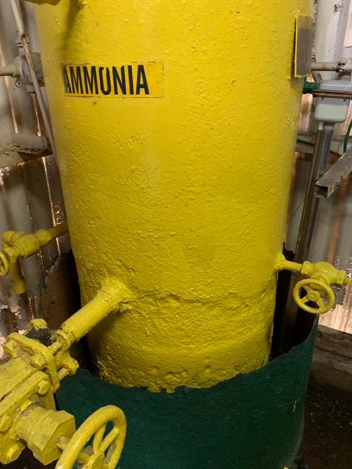
As we can see this is a pressure vessel that is in ammonia service. The process is a mechanical refrigeration process at a chemical facility. The vessel has been in service since 1980. This vessel resides within a “bath” and is used as a “recovery vessel”. When liquid ammonia needs to be removed from a section of the process, operators would move the liquid ammonia to this vessel. The bath would be filled with warm water to aid in the flashing off the ammonia which the vapor is then pulled back into the refrigeration process. As we can see from the picture, the area below the bath wall is where we see severe wall losses and pitting. But as ugly as it looks, we need accurate data to know if we have a serious hazard. Typically in ammonia processes, we see external corrosion and very little internal corrosion.
In order to obtain that data, we need to perform some “thickness testing” per a prescribed RAGAGEP/Procedure and this is where “corrosion allowance” comes into play. Our U-1 form will provide us our nominal wall thickness AND any “corrosion allowance” that the vessel was given. We can see the vessel has some wall loss, BUT how much wall loss is KEY to the assessment of this vessel’s integrity. If the test results show the wall loss is within the acceptable thickness, using the “corrosion allowance” when establishing the minimum wall thickness. In other words, the vessel was designed to loose some wall thickness and as long as we do not exceed the “corrosion allowance” this vessel, as ugly as it may look, may indeed pass it’s thickness test; however there are other concerns with this vessel that may be an issue, as vessel thickness can be impacted by erosion as well.
Here is what the National Board Inspection Code has established as acceptable corrosion damage for liquid ammonia vessels as it relates to corrosion concerns:
(emphasis added by me)
2.3.6.4 LIQUID AMMONIA VESSELS
…
f) Acceptance criteria
…
5) Corrosion
a. For line or crevice corrosion, the DEPTH OF THE CORROSION shall not exceed 25% of the original wall thickness.
b. ISOLATED PITS may be disregarded provided that their depth is NOT MORE THAN 50% of the required thickness of the pressure vessel wall (exclusive of any corrosion allowance), provided the total area of the pits does NOT EXCEED 7 sq. in. (4,500 sq. mm) within any 8 in. (200 mm) diameter circle, and provided the sum of their dimensions along any straight line within that circle does NOT EXCEED 2 in. (50 mm).
c. For a corroded area of considerable size, the thickness along the most critical plane of such area may be averaged over a length NOT EXCEEDING 10 in. (250 mm). The thickness at the thinnest point shall NOT BE LESS THAN 75% of the required wall thickness. When general corrosion is identified that exceeds the limits set forth in this paragraph, the pressure vessel shall be removed from service until it is repaired by an “R” Stamp holder or a fitness-for-service analysis is performed, or the vessel may be permanently retired from service.
It is obvious to me that this vessel’s visual inspection should lead to NDE/NDT immediately so as to obtain the necessary data to make a sound decision on the integrity of this vessel. Personally, I would push hard to have this vessel removed from service until the assessment is completed and begin to ask how does a pressure vessel get to this point without anyone raising any concerns!