
Unfortunately, the code is not as clear as I would like, and I do get a lot of pushback when I encounter high-expansion fluids in hazardous-materials piping. I deal with a lot of liquids that are Highly Toxic, Flammable, and some that are both, which also have a high coefficient of expansion. So, in this article, I hope to explain why B31.3 requires HRVs on some piping and why the code actually requires it.
Let’s first review the requirement: (emphasis by me)
301.2.2 Required Pressure Containment or Relief
(a) Provision shall be made to safely contain or relieve (see para. 322.6.3) any expected pressure to which the piping may be subjected. Piping not protected by a pressure-relieving device, or that can be isolated from a pressure- relieving device, shall be designed for at least the highest expected pressure.
(b) Sources of pressure to be considered include ambient influences, pressure oscillations and surges, improper operation, decomposition of unstable fluids, static head, and failure of control devices.
The primary chemical property that necessitates a hydrostatic relief valve is the Coefficient of Thermal Expansion. When a liquid is trapped in a section of piping, it has nowhere to go as it absorbs heat. Because liquids are largely incompressible, even a small increase in temperature causes the fluid to expand significantly. This expansion exerts an enormous force against the walls of the pipe, fittings, and valves.
The pressure rise (P) in a liquid-filled, “blocked-in” segment can be calculated by looking at the relationship between the fluid’s thermal expansion and the elasticity of the pipe material:
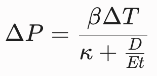
Where:
- B: The coefficient of thermal expansion of the liquid.
- Delta T: The change in temperature.
- K: The isothermal compressibility of the liquid.
- D over E, t: Physical properties of the pipe (diameter, modulus of elasticity, and wall thickness).
While the coefficient of thermal expansion of the liquid (B) is the primary driver, other characteristics of the chemical and the system determine the urgency and design of the relief protection:
| Property | Why it matters for Relief Protection |
| Coefficient of Expansion (B) | High values mean a larger volume increase per degree of temperature rise, causing faster pressure spikes. |
| Compressibility (k) | Liquids with low compressibility resist being squeezed, leading to near-instantaneous pressure spikes as the liquid expands. |
| Vapor Pressure | If the chemical is volatile, it may transition to the vapor/gas phase during heating, which behaves differently under pressure than a pure liquid. |
| Toxicity/Reactivity | Highly hazardous materials (such as bromine, chlorine, or anhydrous ammonia) require a lower risk threshold, making the installation of relief valves an essential safety barrier to prevent catastrophic leaks. |
It is a common misconception that certain chemicals “require” relief valves by virtue of their identity alone. In reality, the requirement is triggered by the interaction between the chemical’s physical properties and the system’s operational design.
- Closed vs. Open Systems: A chemical in an open-ended system (like an overflow line or a tank vent) will never require a hydrostatic relief valve, regardless of its expansion coefficient.
- Operating Temperature Margin: If a system operates at an ambient temperature and is never exposed to external heat sources (such as steam tracing), the potential for Delta T is effectively zero, which may eliminate the need for a HRV.
- Material Limitations: If you are using flexible or thin-walled piping that cannot withstand the potential Delta P calculated in the equation above, we are mandated by ASME B31.3 to provide relief.
When conducting the safety engineering analysis, do not focus solely on the chemical itself. Focus on identifying any segment that can be isolated while liquid-full. If that segment exists, the chemical’s expansion coefficient becomes the deciding factor in how much pressure the pipe wall must withstand before a relief device is required.
Just an FYI: this is NOT driven by PSM or RMP; this pressure protection may be necessary on any liquid piping containing these volatile chemicals. For example, in OSHA’s Ammonia Standard and LPG Standard, HRVs are required:
1910.111(b)(9)(ix) A hydrostatic relief valve shall be installed between each pair of valves in the liquid ammonia piping or hose where liquid may be trapped so as to relieve into the atmosphere at a safe location.
1910.110(b)(10)(xii) A hydrostatic relief valve shall be installed between each pair of shut-off valves on liquefied petroleum gas liquid piping so as to relieve into a safe atmosphere. The start-to-discharge pressure setting of such relief valves shall not be in excess of 500 p.s.i.g. The minimum setting on relief valves installed in piping connected to other than DOT containers shall not be lower than 140 percent of the container relief valve setting and in piping connected to DOT containers not lower than 400 p.s.i.g. The start-to-discharge pressure setting of such a relief valve, if installed on the discharge side of a pump, shall be greater than the maximum pressure permitted by the recirculation device in the system.
I should also point out that many of these chemicals will have their own set of RAGAGEPs, and these RAGAGEPs will require HRVs on piping. But not every chemical will come with its own RAGAGEP, so it is up to the facility engineering group to determine the need.