
With OSHA’s recent revision of their definition of “retail”, there are literally thousands of ammonia facilities that have entered into the world of PSM and have gone from RMP 2 to RMP 3. So this posting is just to offer some insight and/or an alternative to API 510 inspection practices and to help those facilities new to the Mechanical Integrity Inspection requirements understand what a MI inspection should look like for their pressure vessels and RVs.
Vessels in liquid ammonia service are susceptible to stress corrosion cracking (SCC) (see NBIC Part 2, 3.3.2 b)) in areas of high stress. High-strength and coarse-grained materials seem to be more at risk of SCC than are fine-grained or more moderate strength materials, although no commonly used steels appear to be immune to the problem. Postweld heat treatment of new or weld-repaired vessels or cold formed heads is beneficial in reducing the incidence of SCC. The presence of 0.2% minimum water in the liquid ammonia also inhibits SCC. Any leak should be thoroughly investigated and the necessary corrective action initiated.
Internal inspection(s)
1) Where existing openings permit, perform a visual internal inspection of the vessel. Look for any obvious cracks (very advanced SCC) and note areas that are subject to high stress such as welds, welded repairs, head-to-shell transitions, sharp interior corners, and interior surfaces opposite external attachments or supports.
2) Fittings, such as liquid level gage floats and excess flow valves, should be removed or otherwise protected from power buffing or light sandblasting when preparing the interior surface of the vessels for inspection.
3) Vessels in services where liquid ammonia is used as a reactant or is being preheated/vaporized should be inspected for localized corrosion in the reaction or vaporizing zones.
Examination and detection of SCC
1) All interior welds and highly stressed areas should be examined by the Wet Fluorescent Magnetic Particle Testing method (WFMT) using an A/C yoke for magnetization. Note that weld cracks are often transverse in orientation. It is extremely important to ensure that the NDE method used will disclose cracks in any orientation.
2) If cracks are discovered, a calculation shall be made to determine what depth of grinding may be carried out for crack removal (without encroaching on the minimum thickness required by the original code of construction).
3) Where possible, crack removal by grinding is the preferred method of repair. Since the stresses at the crack tips are quite high, even very fine cracking shall be eliminated.
4) Where crack depth is such that removal requires welded repair, a weld procedure shall be employed that will minimize HAZ hardening and residual stresses. Welded repairs, regardless of the depth of the repair, shall be postweld heat treated. The use of alternative welding methods in lieu of PWHT is permitted. Any repairs required and associated postweld heat treatment shall be completed in accordance with NBIC Part 3.
5) Re-inspection by WFMT after welded repair shall be done to ensure complete crack removal.
6) It is not intended to inhibit or limit the use of other NDE evaluation methods. It is recognized that acoustic emission and fracture mechanics are acceptable techniques for assessing structural integrity of vessels. Analysis by fracture mechanics may be used to assess the structural integrity of vessels when complete removal of all ammonia stress cracks is not practical. If alternative methods are used, the above recommendation that all cracks be removed, even fine cracks, may not apply.
In addition to NDE and repair of liquid ammonia vessels that are susceptible to SCC, it is acceptable to use fitness for service evaluation methods to determine the acceptability of a pressure-retaining item to perform its intended function. These methods shall be consistent with NBIC Part 2, 4.4, Methods To Assess Damage Mechanisms And Inspection Frequency For Pressure-Retaining Items.
Inspection of parts and appurtenances
1) If valves or fittings are in place, check to ensure that these are complete and functional. Parts made of copper, zinc, silver, or alloys of these metals are unsuitable for ammonia service and shall be replaced with parts fabricated of steel or other suitable materials.
2) Check that globe valves are installed with the direction of flow away from the vessel.
3) Observe that excess flow valves are properly installed and in good repair.
4) Check that hydrostatic relief valves are installed in the system piping where required.
5) Piping shall be observed to be a minimum of Schedule 80 if threaded and Schedule 40 if welded. Seamless or ERW piping is acceptable. Type F piping shall not be used for ammonia service.
6) Fittings shall be forged or Class 300 malleable iron. Seal welding is permitted only with forged fittings.
7) The Inspector shall note the pressure indicated by the gage and compare it with other gages on the same system. If the pressure gage is not mounted on the vessel itself, it should be ascertained that the gage is installed on the system in such a manner that it correctly indicates actual pressure in the vessel.
8) The Inspector shall note the liquid level in the vessel by observing the liquid level gage or other liquid level indicating device.
Inspection of pressure relief devices
1) See NBIC Part 2, 2.5 for the inspection of pressure relief devices used to prevent the overpressure of liquid ammonia vessels. Pressure relief devices in ammonia service shall not be tested in place using system pressure. Bench testing or replacement is required, depending on the type of pressure relief device used.
2) The Inspector shall note the replacement date marked on vessel safety valves and piping system hydrostatic relief valves requiring replacement every five years.
External inspection of insulated vessels
Acceptance criteria
The following are the acceptance criteria for liquid ammonia vessels. Vessels showing indications or imperfections exceeding the conditions noted below are considered unacceptable.
1) Cracks
Cracks in the pressure vessel boundary (e.g., heads, shells, welds) are unacceptable. When a crack is identified, the vessel shall be removed from service until the crack is repaired by an “R” Stamp holder or the vessel permanently removed from service. (See NBIC Part 3, Repairs and Alterations.)
2) Dents
When dents are identified that exceed the limits set forth below, the vessel shall be removed from service until the dents are repaired by an “R” Stamp holder, a fitness for service analysis is performed, or the vessel permanently retired from service.
a. Dents in shells
The maximum mean dent diameter in shells shall not exceed 10% of the shell diameter, and the maximum depth of the dent shall not exceed 10% of the mean dent diameter. The mean dent diameter is defined as the average of the maximum dent diameter and the minimum dent diameter. If any portion of the dent is closer to a weld than 5% of the shell diameter, the dent shall be treated as a dent in a weld area, as shown in b. below.
b. Dents in welds
The maximum mean dent diameter on welds (i.e., part of the deformation includes a weld) shall not exceed 10% of the shell diameter. The maximum depth shall not exceed 5% of the mean dent diameter.
c. Dents in heads
The maximum mean dent diameter on heads shall not exceed 10% of the shell diameter. The maximum depth shall not exceed 5% of the mean dent diameter. The use of a template may be required to measure dents on heads.
3) Bulges
When bulges are identified that exceed the limits set forth below, the vessel shall be removed from service until the bulges are repaired by an “R” Stamp holder or a fitness for service analysis is performed, the vessel may also be permanently retired from service.
a. Bulges in shells
If a bulge is suspected, the circumference shall be measured at the suspect location and at several places remote from the suspect location. The variation between measurements shall not exceed 1%.
b. Dents in heads
If a bulge is suspected, the radius of the curvature shall be measured by the use of templates. At any point the radius of curvature shall not exceed 1.25% of the diameter for the specified shape of the head.
4) Cuts or gouges
When a cut or gouge exceeds 25% of the thickness of the vessel, the vessel shall be removed from service until it is repaired by an “R” Stamp Holder or a fitness-for-service analysis is performed. The vessel may also be permanently retired from service.
5) Corrosion
a. For line or crevice corrosion, the depth of the corrosion shall not exceed 25% of the original wall thickness.
b. Isolated pits may be disregarded provided that their depth is not more than 50% of the required thickness of the pressure vessel wall (exclusive of any corrosion allowance), provided the total area of the pits does not exceed 7 sq. in. (4,500 sq. mm) within any 8 in. (200 mm) diameter circle, and provided the sum of their dimensions along any straight line within that circle does not exceed 2 in. (50 mm).
c. For a corroded area of considerable size, the thickness along the most critical plane of such area may be averaged over a length not exceeding 10 in. (250 mm). The thickness at the thinnest point shall not be less than 75% of the required wall thickness. When general corrosion is identified that exceeds the limits set forth in this paragraph, the pressure vessel shall be removed from service until it is repaired by an “R” Stamp holder or a fitness-for-service analysis is performed, or the vessel may be permanently retired from service.
RECOMMENDED INSPECTION AND TEST FREQUENCIES FOR PRESSURE RELIEF DEVICES
Pressure vessels and piping
Frequency of test and inspection of pressure relief devices for pressure vessel and piping service is greatly dependent on the nature of the contents and operation of the system and only general recommendations can be given. Inspection frequency should be based on previous inspection history. If valves are found to be defective or damaged by system contents during inspection, intervals should be shortened until acceptable inspection results are obtained. Where test records and/or inspection history are not available, the inspection frequencies in Table 2.5.8 are suggested.
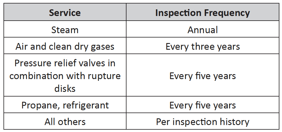
DETERMINING INSPECTION INTERVALS
a) The maximum period between internal inspections or a complete inservice evaluation of pressure-retaining items shall not exceed one-half of the estimated remaining service life of the vessel or ten years, whichever is less. The method for estimating inspection intervals of pressure-retaining items subject to internal erosion or corrosion is discussed in NBIC Part 2, 4.4.7.1 and 4.4.7.2.
b) Inspection intervals can be revised beyond the maximum period stated above, provided the owner or user has submitted technical justification for revising the inspection interval, subject to review and acceptance by the Jurisdiction, where required.
c) Data used in engineering assessment methods to develop revised inspection intervals for pressure-retaining items shall be re-evaluated every five years, when a change in operation occurs, or after discovery of new and/or altered damage mechanisms.
METHOD FOR ESTIMATING INSPECTION INTERVALS FOR PRESSURE RETAINING ITEMS SUBJECT TO EROSION OR CORROSION
Assessment guidelines for pressure-retaining items subject to corrosion or erosion are provided in this Section. These guidelines are based on actual thickness measurements within the area of concern. Minimum required wall thickness shall be based on allowable stress of the material. Applicability and limitations of this guideline are as follows:
a) Original design criteria are known;
b) Item is not operating in the creep range;
c) Item does not contain crack-like indications;
d) Service stresses are known; and
e) Maintenance and operating history are known.
HOSES – NEW OR REPLACED DELIVERY HOSE ASSEMBLIES
The operator shall repair hose assemblies and place the cargo tank back in service if retested successfully in accordance with the following:
a) The new and/or replaced hose assembly is tested at a minimum of 120% of the hose’s MAWP;
b) The operator shall visually examine the delivery hose assembly while it’s under pressure;
c) If the test is successful, the operator shall ensure that the delivery hose assembly is permanently marked with the month and year of the test; and
d) It should be noted that after July 1, 2000, the operator shall complete a record documenting the test and inspection, which shall include the following:
1) The date and signature of the Inspector that performed the inspection;
2) The owner of the hose assembly;
3) The hose identification number;
4) The date of the original delivery of the hose assembly and tests;
5) Notes of any defects observed;
6) Any repairs that may have been made; and
7) Identification in the written report that the delivery hose assembly passed or failed the tests and inspections.