
Flammable Liquids and Piping Design (IFC 2018)

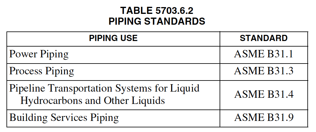
IFC 2018 TABLE 5703.6.2 PIPING STANDARDS

The 2018 IFC has some great design requirements for flammable liquids (as does NFPA 30).  Abiding by this 2018 IFC, Chapter 57 would provide a much higher degree of safety as compared to meeting OSHA’s 1910.106.  So I have broken down and discussed these IFC requirements for those looking to improve their flammable liquid piping systems:

(emphasis added by me)

5703.5.2 Location.    Signs shall be posted in locations as required by the fire code official. Piping containing flammable liquids shall be identified in accordance with ASME A13.1.

Pipe labeling for piping containing flammable liquids falls under ANSI/ASME A13.1 – 2007 Standard for the Identification of Pipes. These labels MUST be in English text and have arrows to indicate flow direction.

5703.5.4 Identification.  Color coding or other approved identification means shall be provided ON EACH LOADING AND UNLOADING RISER for flammable or combustible liquids to identify the contents of the tank served by the riser.

More than one flammable or combustible liquid may be present at a facility in addition to other liquids. The loading and unloading risers are to be color coded or identified by other approved identification means to ensure that operators know which material is being used. If color coding is not used, the fire code official is to approve any other identification means.

5703.6 Piping systems.  Piping systems, and their component parts, for flammable and combustible liquids shall be in accordance with Sections 5703.6.1 through 5703.6.11.

Piping must be designed to provide protection against overpressure or other conditions that could create leaks at joints or rupture the pipes.

5703.6.1 Nonapplicability.  The provisions of Section 5703.6 shall NOT apply to gas or oil well installations; piping that is integral to stationary or portable engines, including aircraft, watercraft and motor vehicles; and piping in connection with boilers and pressure vessels regulated by the International Mechanical Code.
5703.6.2 Design and fabrication of piping systems and components.
Piping system components shall be designed and fabricated in accordance with the applicable standard listed in Table 5703.6.2 and Chapter 27 of NFPA 30, except as modified by Section 5703.6.2.1.

This section follows along with Chapter 27 of NFPA 30, which references the ASME B31 series of piping standards, not all of which are suitable or necessary for flammable or combustible liquid piping. By including a table listing the four specific standards within ASME B31 that are applicable for flammable liquid piping, the code is made more user-friendly. It is left to the code user to select the correct standard to apply.

IFC 2018 TABLE 5703.6.2 PIPING STANDARDS
5703.6.2.1 Special materials.  Low-melting-point materials (such as aluminum, copper or brass), materials that soften on fire exposure (such as nonmetallic materials) and nonductile material (such as cast iron) shall be acceptable for use underground in accordance with the applicable standard listed in Table 5703.6.2. Where such materials are used outdoors in above-ground piping systems or within buildings, they shall be in accordance with the applicable standard listed in Table 5703.6.2 and one of the following: 
1. Suitably protected against fire exposure.
2. Located where leakage from failure would not unduly expose people or structures.
3. Located where leakage can be readily controlled by operation of remotely located valves in a location provided with ready access.
In all cases, nonmetallic piping shall be used in accordance with Section 27.4.6 of NFPA 30.
5703.6.3 Testing.  Unless tested in accordance with the applicable section of ASME B31.9, piping, before being covered, enclosed or placed in use, shall be HYDROSTATICALLY tested to 150 percent of the maximum anticipated pressure of the system, or PNEUMATICALLY tested to 110 percent of the maximum anticipated pressure of the system, but not less than 5 pounds per square inch gauge (psig) (34.47 kPa) at the highest point of the system. This test shall be maintained for a sufficient time period to complete visual inspection of joints and connections. For not less than 10 minutes, there shall be no leakage or permanent distortion. Care shall be exercised to ensure that these pressures are NOT applied to vented storage tanks. Such storage tanks shall be tested independently from the piping.

Piping must be tested to a minimum pressure of 5 pounds per square inch gauge (psig) (34.47 kPa) or to a pressure greater than the anticipated pressure of the system. The pipe joints and connections are to be visually inspected. The test pressure is to be maintained for a minimum of 10 minutes, but not less than the time required for a visual inspection.

5703.6.3.1 Existing piping. Existing piping shall be tested in accordance with this section where the fire code official has reasonable cause to believe that a leak exists. Piping that could contain flammable or combustible liquids shall NOT be tested pneumatically. Such tests shall be at the expense of the owner or operator.

Exception: Vapor-recovery piping is allowed to be tested using an inert gas.

The fire code official may require testing of existing piping. Existing piping is to be tested to the same criteria as new piping, except that piping containing flammable or combustible liquids is not to be pneumatically tested. The introduction of air into these pipes can create a vapor and air mixture that reaches the flammable range.  The exception allows pneumatic testing of a vapor recovery system with an inert gas (such as nitrogen or carbon dioxide). Because vapor-recovery systems are designed to remove the flammable or combustible vapors and recycle the liquid, these vapors could be removed from the piping during the recovery process; however, the inert gas is still required to prevent the vapor and air mixture from reaching the flammable range before or during the recovery process.

5703.6.4 Protection from vehicles.  Guard posts or other approved means shall be provided to protect piping, valves or fittings subject to vehicular damage in accordance with Section 312.

Protection from vehicle impact is provided by bollards or other approved barriers. IFC, Section 312, VEHICLE IMPACT PROTECTION provides the specifications for bollards or the design forces required for an approved barrier to comply with the code.

5703.6.5 Protection from external corrosion and galvanic action.  Where subject to external corrosion, piping, related fluid-handling components and supports for both underground and above-ground applications shall be fabricated from noncorrosive materials, and coated or provided with corrosion protection. Dissimilar metallic parts that promote galvanic action shall not be joined.

Deterioration of piping and components can cause leaks and spillage of flammable and combustible liquids. Using noncorrosive materials, protective coatings, galvanic protection or a combination of these methods can protect the piping and components. Dissimilar metals are prohibited because of the localized galvanic action that could occur between them. This localized galvanic action could cause one of the metals to corrode while the other metal is protected from corrosion. See Section 5704.2.7.9 for corrosion protection for tanks.

5703.6.6 Valves.  Piping systems shall contain a sufficient number of manual control valves and check valves to operate the system properly and to protect the plant under both normal and emergency conditions. Piping systems in connection with pumps shall contain a sufficient number of such valves to control properly the flow of liquids in normal operation and in the event of physical damage or fire exposure.

Valves are essential to proper operation. Check valves prevent the backflow or siphonage of flammable and combustible liquids. Isolation/Stop valves are used to isolate piping sections and equipment for maintenance. Valves are also used to stop the flow of flammable liquids in the event of an emergency.

5703.6.6.1 Backflow protections.  Connections to pipelines or piping by which equipment (such as tank cars, tank vehicles or marine vessels) discharges liquids into storage tanks shall be provided with check valves or block valves for automatic protection against backflow where the piping arrangement is such that backflow from the system is possible.  Where loading and unloading is done through a common pipe system, a check valve is not required.  However, a block valve, located in an area where it is provided with ready access or remotely operable, shall be provided.

Check valves prevent the backflow or siphonage of flammable and combustible liquids. A check valve cannot be used for a common pipe used to both load and unload flammable and combustible liquids because check valves are designed to allow flow in only one direction. This type of valve would prohibit a common pipe for both loading and unloading.

A block valve is to be used for “common” pipe. The block valve control mechanism must be provided with ready access or remotely operable in the event that the valve is needed to stop a spill or accidental discharge.

5703.6.6.2 Manual drainage.  Manual drainage-control valves shall be located at approved locations REMOTE from the tanks, diked area, drainage system and impounding basin to ensure their operation in a fire condition.

In case of a fire, it may be necessary to drain the piping system. This is to be accomplished by a manual drainage-control valve. The number of manual drainage-control valves will depend on the facility. The manual drainage-control valves are to be located to isolate sections of the piping and equipment for maintenance, repair, replacement and control of flammable and combustible liquids during an emergency.

5703.6.7 Connections.  Above-ground tanks with connections located below normal liquid level shall be provided with internal OR external ISOLATION VALVES located as close as practical to the shell of the tank. Except for liquids whose chemical characteristics are incompatible with steel, such valves, where external, and their connections to the tank shall be of steel.

The isolation valve is located as near as practical to above-ground tanks to control the flow of flammable and combustible liquids. This location is to reduce the quantity of flammable and combustible liquids that may be discharged during an emergency. The loss of a portion of the piping system between an aboveground tank and the isolation valve may allow the discharge of the flammable and combustible liquids under gravity flow.

The isolation valve is to be of steel unless the flammable and combustible liquids are not compatible with steel. Other valve materials may be damaged and fail under the heat from a fire. If the isolation valve fails, the flammable and combustible liquids may be discharged under gravity flow and increase the fire potential.

5703.6.8 Piping supports.  Piping systems shall be substantially supported and protected against physical damage and excessive stresses arising from settlement, vibration, expansion, contraction or exposure to fire. The supports shall be protected against exposure to fire by one of the following: 1. Draining liquid away from the piping system at a minimum slope of not less than 1 percent.  2. Providing protection with a fire-resistance rating of not less than 2 hours.  3. Other approved methods.  Pipe supports are necessary to reduce stress on the pipe from both external and internal sources.

Personnel are an external source of potential damage to piping, as is unattached equipment hitting the piping system. The pipe supports are to absorb these impact loads to protect the pipe from excess deflection.  Internal forces are caused by the positive and negative pressures created by the operation of pumps and valves. Pumping of flammable and combustible liquids will generate positive pressure in the pipe. This pressure, combined with any pressure required to support the dead weight of the piping system and flammable and combustible liquids in the piping system, can cause the pipe wall to fail. The pumping action and the operation of the valve can cause shock waves to travel through the liquids in the pipe, which can create internal pressures several times larger than normal operating pressures. One type of shock wave is caused by the fast opening and closing of a valve.  This pressure wave can place high internal pressures on the piping system. This section lists three methods of protecting pipe supports from a fire.  The fire code official has the responsibility to review these alternative methods and the authority to approve an alternative method, but only if it has been demonstrated or documented to comply with the intent of the code requirement.

5703.6.9 Flexible Joints.  Flexible joints shall be listed and approved and shall be installed on underground liquid, vapor and vent piping at all of the following locations:  1. Where piping connects to underground tanks.  2. Where piping ends at pump islands and vent risers.  3. At points where differential movement in the piping can occur.

Flexible joints are necessary to handle the expansion and contraction of the piping system and control vibration. Expansion and contraction of the piping system will create stresses in the pipe and pipe joints because of the increase or decrease in pipe length. These changes in pipe length may cause the pipe to buckle, or pull or push a joint apart.

The vibration of a pipe may cause a fatigue failure. Fatigue failures result from the reversal of stresses in a material. The flexing of the pipe wall or pipe joint from a positive pressure to a negative pressure over time will create a fatigue failure in the pipe wall. This fatigue can cause the pipe or pipe joint to finally fail because of internal operating pressures or external loads, such as dead weight or an impact load. This section lists three locations where flexible joints must be used.

5703.6.9.1 Fiberglass-reinforced plastic piping.   Fiberglass-reinforced plastic (FRP) piping is not required to be provided with flexible joints in locations where both of the following conditions are present: 1. Piping does not exceed 4 inches (102 mm) in diameter.  2. Piping has a straight run of not less than 4 feet (1219 mm) on one side of the connection where such connections result in a change of direction.  In lieu of the minimum 4-foot (1219 mm) straight run length, approved and listed flexible joints are allowed to be used under dispensers and suction pumps, at submerged pumps and tanks, and where vents extend above ground.

Fiberglass-reinforced plastic piping is more flexible than metal piping. This flexibility of fiberglass-reinforced plastic piping can be used to handle expansion and contraction of piping or vibrations that would be handled by a flexible joint under a set of conditions of pipe diameter and the minimum straight section of fiberglass-reinforced plastic piping.

This section lists two conditions that must be met:

1. Maximum 4 inches (102 mm) in diameter. Fiberglass-reinforced plastic piping greater than 4 inches (102 mm) in diameter can be too stiff to have the flexibility necessary to be an alternative to a flexible joint. The greater the diameter of the pipe, the greater the stiffness of the pipe.

2. Minimum 4-foot (1219 mm) straight run. Straight runs of less than 4 feet (1219 mm) are too stiff to have the flexibility necessary to be an alternative to a flexible joint. The longer a pipe run is, the more the pipe can flex without causing stresses that will damage the pipe.

These two conditions are required before fiberglass-reinforced plastic piping can be used without flexible joints. Flexible joints can be used with fiberglass fiberglass-reinforced plastic piping where there is not sufficient space to meet the two conditions or where the use of fiberglass-reinforced plastic piping is not desired. These locations can use flexible joints.

5703.6.10 Pipe joints.  Joints shall be liquid tight and shall be welded, flanged or threaded except that listed flexible connectors are allowed in accordance with Section 5703.6.9. Threaded or flanged joints shall fit tightly by using approved methods and materials for the type of joint. Joints in piping systems used for Class I liquids shall be welded where located in concealed spaces within buildings.  Nonmetallic joints shall be approved and shall be installed in accordance with the manufacturer’s instructions.  Pipe joints that are dependent on the friction characteristics or resiliency of combustible materials for liquid tightness of piping shall not be used in buildings. Piping shall be secured to prevent disengagement at the fitting.

Pipe joints are to be liquid tight. The code recognizes only three types of generic mechanical joints as being adequate for pipes carrying flammable and combustible liquids. Welded joints, flanged joints and threaded joints provide a liquid-tight joint. ASME B31.3 contains criteria for the welding of piping.  Flanged joints are to be made with materials that are compatible with the piping system and the flammable and combustible liquids in the pipe. Threaded joints are to be fabricated by methods that ensure a liquid-tight joint by the selection of thread pitch and length of the threaded connection. Listed flexible joints are to be approved by the fire code official. Pipe joints in a building’s concealed space that carry Class I flammable liquids are limited to welded joints. Because Class I flammable liquids can become vapor at ambient temperature, a joint leak in a concealed space could go unnoticed. There could be no liquid escaping the concealed space for personnel to notice. A welded joint that has passed the test requirements of Section 5703.6.3 would be a liquid-tight joint that meets code requirements.

5703.6.11 Bends.  Pipe and tubing shall be bent in accordance with ASME B31.9. Pipe direction can be changed using either fittings or bends. Bends are to be done according to ASME B31.9.Bending a pipe can damage the pipe. An improper bend may kink the interior portion of the pipe wall and that could cause increased pipe stresses resulting from the kink restricting flow. An improper bend could stretch the outer portion of the pipe wall. The stretched portion of pipe would have a thinner wall thickness. This thinner wall could develop pinhole leaks or even cause the pipe to rupture.
Scroll to Top