
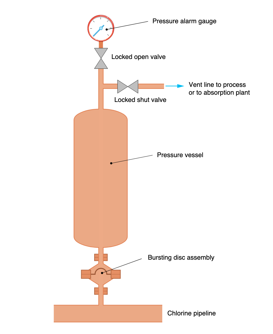
 We visit this topic once again as I have already spent time with a “former client” who is now in a serious bind with both OSHA and EPA after a significant Chlorine (Cl2) release. They are a former client as they fired me after a 5-year PHA and 3-year audit a number of years ago. They hired me because of their frustrations regarding the handling of their Cl2 and their inability to control it. They were one of the clients who thought I was certifiable crazy and wondered where on earth I kept getting all of these “crazy designs” for such a “small process”. During their 5-year PHA revalidation, which was more like an initial PHA, it was discovered during the opening meeting and our process walk-down that the process, although small on a grand scheme of things, had no hydrostatic relief protection on the liquid pipe runs. This of course was identified as a serious design error, which then led me to ask what RAGAGEP was used to design and construct the process. And you can guess what caused this latest RQ release of Cl2… pipe failure due to trapped liquid Cl2 from when they shut down their process WITHOUT following their Normal Shutdown SOP and left liquid Cl2 in the piping (Note this was one of the COVID-19 releases I mentioned a few weeks ago). Once we got some summer temps, the pipe catastrophically failed (quite dramatically I might add) and released the Cl2. Of course, both OSHA and EPA, went right to the point of release and asked how it happened and their next question was “doesn’t the Chlorine Institute piping pamphlet require expansion protection?” So I ask again… Why do so many process engineers hate hydrostatic relief systems?
In this article, I will explain the two types of Hydrostatic Relief Designs: Open and Closed, and when we should use either system. As we have discussed before, several OSHA standards and RAGAGEPs require hydrostatic relief systems, with the most common in my career being Propane/LPG, Chlorine, and Anhydrous Ammonia.
When we look at LPG, Cl2, and NH3 we see three (3) extremely hazardous substances (EHS); the LPG due to its flammability and Cl2 and NH3 for their toxic properties. All three have one thing in common – they have very low boiling points along with very high vapor pressures, which means that if we trap them in liquid form, they will expand when heated and these expansion values can be “off-the-charts” crazy, such as an increase in 1° results in a pressure increase of 150 psi. This is why OSHA requires piping where we can find NH3 or LPG in the liquid form to be protected from this expansion. OSHA does not have a Chlorine standard, but the Chlorine Institute does have a standard/pamphlet that requires hydrostatic protection on piping (Pamphlet 6, PIPING SYSTEMS FOR DRY CHLORINE, EDITION 15).
For those who have not read my previous articles on this topic, here are the OSHA references:
LPG
1910.110(b)(10)(xii) A hydrostatic relief valve shall be installed between each pair of shut-off valves on liquefied petroleum gas liquid piping so as to relieve into a safe atmosphere. The start-to-discharge pressure setting of such relief valves shall not be in excess of 500 p.s.i.g. The minimum setting on relief valves installed in piping connected to other than DOT containers shall not be lower than 140 percent of the container relief valve setting and in piping connected to DOT containers not lower than 400 p.s.i.g. The start-to-discharge pressure setting of such a relief valve, if installed on the discharge side of a pump, shall be greater than the maximum pressure permitted by the recirculation device in the system.
NH3
1910.111(b)(9)(ix) A hydrostatic relief valve shall be installed between each pair of valves in the liquid ammonia piping or hose where liquid may be trapped so as to relieve into the atmosphere at a safe location.
Cl2
2. GENERAL
2.1 PRECAUTIONS
Chlorine is a hazardous material. It is normally used and processed as a liquid or gas under pressure. For general precautions in chlorine handling, the reader should refer to CI Pamphlet 1 (13.1). This pamphlet outlines practices that industry has found to be safe and environmentally sound. Extraordinary practices such as the use of double wall piping are not required as long as the system is installed, maintained and inspected per the recommendations contained herein.
Particular care must be taken as follows:
…
b) Protect piping from overpressure where chlorine can be trapped between closed valves. Liquid chlorine has an unusually high coefficient of thermal expansion that can cause piping to rupture as temperature increases, unless the piping system is protected with items such as expansion chambers, relief devices, or other suitable means.
So with all three (3) of these EHS’s requiring hydrostatic expansion protection, both by science and compliance, which type of system is acceptable for each one?
Well, that all depends on which chemical we are dealing with and where the relief system would discharge. For example, with Cl2 we NEVER EVER discharge to the atmosphere! Cl2 is super hazardous (IDLH = 10 ppm) and we never want to let that tiger out of its cage even in the SMALLEST of quantities! So regardless of where the RV discharges, with Cl2 we will ALWAYS capture the discharge. And it just so happens the Chlorine Institute has provided us with an EXCELLENT RV system design for just this purpose. (See Drawing 136 in Pamphlet 6, also shown below).
For LPG we have a choice, depending on where the LPG would discharge to. Usually, with a properly functioning hydrostatic RV, the amount of LPG release will be minimal, and in a WELL VENTILATED area such as OUTSIDE, we usually discharge our LPG to the atmosphere. I have seen this done as well inside a large industrial building that has some serious ventilation – although I would have never been allowed to do this for the companies I have worked for as a Safety Engineer – they ALWAYS required the EHS from a hydrostat to be vented outside. This required our pipe runs to be near an outside wall of the building. And realize this, these spaces (both in LPG and NH3 service) were well-ventilated spaces with 6-10 air changes per hour AND they were designed as Class I, Div 2 HAZLOCs! NH3 was managed much like LPG. We always vented our hydrostats outside an enclosed space.
So with that all being said, what does a hydrostatic relief system look like when they don’t vent to the atmosphere nor to a destruction device such as a scrubber? It just so happens that our friends at the Chlorine Institute have been using such a design for decades and it is quite simple; so simple I am not sure why other industries have not stolen it for their process designs. (NOTE: I have seen this design on a few “lethal service” processes that were not Cl2)
For example, some ammonia refrigeration processes have liquid NH3 lines run inside their facility with several of these lines running through normally occupied spaces. Some of these lines have failed due to trapped liquid from operator error(s) and these events have caused many injuries, property damage, and lost production. So why wouldn’t the refrigeration industry want these runs of piping in these high-risk areas protected by such a simple design? Beats me, but the push back is massive when it is suggested in an engineering review, PHA, Audit, etc.
Here is the design:
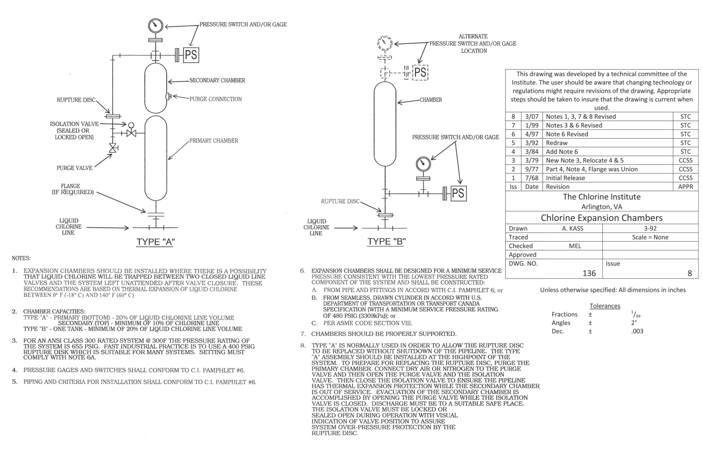
As we can see above, this is a CLOSED system, meaning once the rupture disc is blown the chamber collects and holds the EHS. This means that once the emergency system has been activated it REQUIRES IMMEDIATE ATTENTION. Both designs, A & B, include a PRESSURE GAUGE and/or SWITCH (alarm). I always have either a Tell-Tale gauge or an alarm indicator on my systems and have even seen some systems with an interlock to take actions once a chamber is activated.
Because this is a CLOSED system, we will need the means to evacuate the EHS from the chamber. And know this, if we activate one of these systems, we will have to evacuate the entire section of piping in order to evacuate the chamber AND to replace the RD safely – AND BOTH of these will REQUIRE a written SOP, Line Break/Equipment Opening permit, and a PPE Hazard Assessment. And as I pointed out in my other hydrostatic RV article this week, we could be talking about 13 gallons of Cl2 we will have to evacuate, which corresponds to a liquid 1″ pipe that is 325′ long. And some may balk at 13 gallons of Cl2; but trust me, this would be a VERY BAD DAY if we lost 13 gallons (169 pounds) of Cl2!!! Keeping in mind that the RQ is just 10 pounds and the IDLH for Cl2 is 10 ppm. But this takes us back full circle as to why we need the hydrostatic protection and the discharge from this relief system is EITHER CLOSED or vented to a destruction device and NEVER to the atmosphere.